Scroll to:
Structure and properties of antifriction Ti–Cr–Ni–Cu–Sn–P–C–N coatings deposited by magnetron sputtering of composite SHS targets
https://doi.org/10.17073/1997-308X-2025-3-60-73
Abstract
This article focuses on the production of wear-resistant antifriction coatings by magnetron sputtering using composite SHS-fabricated cathode targets of TiCrNiC and TiCrNiC–CuSnP in Ar and Ar + 15 % N2 atmospheres. Special attention is given to the phase composition and structure of the targets, produced via the self-propagating high-temperature synthesis (SHS) method. Structural characterization of the targets and coatings was carried out using X-ray diffraction (XRD), scanning electron microscopy (SEM), energy-dispersive spectroscopy (EDS), and glow discharge optical emission spectroscopy (GDOES). The mechanical and tribological properties of the coatings were evaluated using nanoindentation, scratch testing, and pin-on-disk sliding wear tests. The resulting coatings exhibited dense, defect-free microstructures with a uniform elemental distribution through the thickness. The coating matrix was primarily composed of FCC phases c-TiC(N) and c-(Ni,Cr). The addition of copper to the coating led to the formation of an additional amorphous Cu-based phase. The coatings demonstrated hardness in the range of 18–21 GPa and an elastic modulus of 220–235 GPa. High critical loads for adhesive failure were observed, reaching up to 60 N. The non-reactive Ti–Cr–Ni–C coatings exhibited the lowest friction coefficients (0.17–0.18), while other compositions showed values ranging from 0.22 to 0.25, in contrast to 0.63–0.71 for uncoated steel substrates. The specific wear rate varied between 1.1·10–6 and 5.0·10–6 mm3/(N·m) depending on the counterbody material and coating composition, which is nearly two orders of magnitude lower than that of the substrate material ((1.2÷2.7)·10–4 mm3/(N·m).
Keywords
For citations:
Kiryukhantsev-Korneev P.V., Chertova A.D., Pogozhev Yu.S., Levashov E.A. Structure and properties of antifriction Ti–Cr–Ni–Cu–Sn–P–C–N coatings deposited by magnetron sputtering of composite SHS targets. Powder Metallurgy аnd Functional Coatings (Izvestiya Vuzov. Poroshkovaya Metallurgiya i Funktsional'nye Pokrytiya). 2025;19(3):60-73. https://doi.org/10.17073/1997-308X-2025-3-60-73
Introduction
As the potential of consolidated materials has been largely exhausted, the development of new high-performance engineering systems is no longer possible without surface modification technologies and the use of functional coatings. Today, considerable attention is focused on the design of coatings for protecting critical components operating in aggressive liquid and gaseous environments and under various wear conditions. Among the most promising are titanium carbide and carbonitride-based coatings, which exhibit high hardness, wear and corrosion resistance, and pronounced antifriction properties [1–3].
By adjusting the stoichiometry of TiCN coatings, it is possible to tailor their mechanical and tribological performance by controlling the structural type, internal stresses, and the concentration of free carbon, which acts as a solid lubricant in the tribological contact zone [4; 5]. At a C/N ratio close to 1, record hardness values of up to 45 GPa have been reported, attributed to significant compressive stresses (–6 GPa) arising from distortions in the FCC lattice structure [6]. In contrast, coatings with an elevated carbon content (C/N = 5.6) achieved a friction coefficient of ~0.1 [5]. In these coatings, carbon atoms formed amorphous intergranular layers along TiCN crystallite boundaries, resulting in a nanocomposite structure described as nc-TiCN/a-C, where nc denotes nanocrystallites and a the amorphous phase.
The performance of TiCN coatings can be further enhanced by the addition of metallic elements [7–12]. For instance, aluminum improves both wear and oxidation resistance [7; 8], while nickel and chromium exhibit similar effects [9; 10]. These improvements are attributed to the formation of dense oxide films on the coating surface during heating in air, which inhibit oxygen penetration into the bulk material.
In recent years, copper-based coatings have attracted growing interest [13–15] due to copper’s relatively low friction coefficient and high thermal conductivity, which is crucial for efficient heat dissipation from the contact zone. Copper can be introduced either in its pure form or as part of brass or bronze alloys, offering excellent antifriction performance at relatively low cost [16]. Notably, the incorporation of ductile metals into ceramic matrices underpins the concept of nanocomposite superhard coatings (hardness >40 GPa), as proposed by the author in [17]. This concept involves the formation of nc-MeN/metal structures (where Me = Ti, Cr, Zr, etc., and metal = Cu, Ni, Fe, etc.), with the MeN phase consisting of nanocrystallites and the metallic phase being X-ray amorphous. Furthermore, all grains are expected to exhibit a preferred orientation [17; 18]. Subsequent research extended this concept to carbide-based systems such as Ti–Cu–C [19], and nanocomposite nc-TiCN/a-Cu coatings with a hardness of 37 GPa were reported in [20].
Various methods can be used to deposit titanium carbide and carbonitride coatings, including those alloyed with transition metals. These methods include plasma spraying [21], electric arc cladding [22], laser cladding [23], electro-spark deposition [11; 24; 25], chemical vapor deposition [26], vacuum cathodic arc evaporation [27], and pulsed laser deposition [28]. Among these, magnetron sputtering stands out as a highly promising technique, allowing the deposition of wear-resistant and antifriction coatings across a broad compositional range. The method yields coatings with low impurity levels, minimal defects, and smooth surfaces that require no post-processing [1; 12; 29–31]. The capabilities of magnetron sputtering are further enhanced when multicomponent ceramic targets produced via self-propagating high-temperature synthesis (SHS) are used [32; 33]. This approach ensures that the atomic flux from the cathode to the substrate contains all necessary metallic and non-metallic elements, providing high compositional homogeneity across the coating thickness. A promising material for fabricating SHS-based sputtering targets is the STIM-3B alloy (Ti–Cr–C–Ni system), whose combustion and structure formation mechanisms have been studied in detail [34]. Tin–phosphor bronze powder can also be used as an alloying addition in target preparation.
The aim of this study was to develop tribological coatings of Ti–Cr–Ni–C–(N) and Ti–Cr–Ni–Cu–Sn–P–C–(N) compositions by magnetron sputtering using multicomponent SHS targets in Ar and Ar–N2 atmospheres. Particular emphasis was placed on the synthesis of targets with tailored compositions.
Materials and methods
The starting materials used for fabricating the cathode targets were titanium powder (Ti) grade PTS (<60 µm), chromium powder (Cr) grade PX-1S (<63 µm), nickel powder (Ni) grade PNK-OT2 (<71 µm), technical carbon black (C) grade P804-T with a specific surface area of 15 m2/g, graphite powder (Cgr) grade MG-1, and tin-phosphor bronze alloy powder (BrOF grade; composition: Cu–7.8 wt. % Sn–0.48 wt. % P; particle size 100–200 µm). The compositions of the reactive mixtures for SHS-based target synthesis were calculated assuming complete chemical transformation according to the following equation
[70.775 % (Ti + C) – 19.475 % (3Cr + 2C) – 5 % Cgr – 4.75 % Ni] + X % Bronze,
where X is the bronze content in the charge, set to 0 or 20 wt. %. The compositions of the powder mixtures are summarized in Table 1.
Table 1. Experimental compositions of initial powder mixtures
| ||||||||||||||||||||||||||||||||||||||||||
Before mixing, all starting powders were dried at 100 °C for 24 h. Mixing was performed in a 3 L rotary ball mill for 8 h using cemented carbide grinding balls at a powder-to-ball mass ratio of 1:8.
The adiabatic combustion temperature (\(T_{\rm{c}}^{{\rm{ad}}}\)), as well as the equilibrium phase composition and the physical state of the SHS products at \(T_{\rm{c}}^{{\rm{ad}}}\), were calculated using the THERMO software package [35]. Composite cathode targets of TiCrNiC and TiCrNiC–CuSnP with dimensions diameter 120 mm × 10 mm were produced using pressure-assisted self-propagating high-temperature synthesis SHS, as described in [33].
The powder mixtures were pre-compacted to 60 % of theoretical density in a steel cylindrical mold at 70 atm. The green compacts were further dried in a vacuum oven at 100 °C for 4 h to remove residual moisture and adsorbed gases. The key parameters for SHS under pressure were as follows: applied pressure – 200 atm; ignition delay – 1 s; dwell time under pressure – 5 s. The synthesis was carried out in a sand mold using a DA-1532B hydraulic press. The resulting billets were then ground and shaped to the required dimensions using EDM cutting.
The phase composition of the synthesized samples was analyzed using a DRON 4-07 X-ray diffractometer (Russia) with monochromatic CuKα radiation. Scans were collected pointwise over a 2θ range of 10–110°, with a step size of 0.1° and exposure time of 3 s per step. The microstructure was examined using a scanning electron microscope (SEM) S-3400N (Hitachi, Japan) equipped with a NORAN 7 EDS system (Thermo Scientific, USA), operated at accelerating voltages of 5–20 kV.
Coating deposition was performed using a UVN-2M vacuum unit equipped with gas inlets, a substrate positioning system, a slit-type ion source, and two magnetrons powered by Advanced Energy DC Pinnacle Plus units (USA), as described in [36]. Substrates included diameter 30 mm disks of SCM440 steel (equivalent to 40KhFA steel) for mechanical and tribological testing, and VK6M cemented carbide for compositional and adhesion strength analysis. The substrates were polished using a Struers RotoPol-21 system (Denmark). Surface cleaning was performed in an ultrasonic disperser using sequential treatments with gasoline, solvent, and isopropanol. Additionally, model substrates of monocrystalline silicon KÉF-4.5 (100) (Elma, Russia), sized 15×15 mm, were coated for structural analysis. Both base and model substrates were coated under identical conditions. Prior to deposition, substrates were cleaned using ion etching (0.03 Pa, 2 kV, 60 mA, Ar+ ions). During coating deposition, the magnetron current was 1.5 A, the voltage 500 V, the power supply frequency 50 kHz, the bias voltage –50 V, the working pressure 0.2 Pa, and the process duration was 10 min. The nitrogen content in the Ar + N2 gas mixture (gas purity 99.999 %) was varied between 0 and 15 %.
The compact ceramics and coatings were examined by scanning electron microscopy (SEM) and energy-dispersive spectroscopy (EDS) using an S-3400 microscope (Hitachi, Japan) equipped with a Noran 7 spectrometer (Thermo Scientific, USA). X-ray diffraction (XRD) analysis of the ceramic specimens was performed using a DRON 4-07 diffractometer (Russia), while coatings were analyzed using a D8 Advance diffractometer (Bruker, Germany). Diffraction data were collected using monochromatized CuKα radiation with a step size of 0.1° and an exposure time of 10 s per step; the total scan duration was 1 h. Phase identification was carried out using the EVA software package and the PDF2 international database. The elemental composition of the coatings and their depth distribution profiles were determined using glow discharge optical emission spectroscopy (GDOES) on a Profiler-2 spectrometer (Horiba Jobin Yvon, France) [37].
Hardness (H) and elastic modulus (E) of the coatings were determined by nanoindentation using a Nano-Hardness Tester (CSM Instruments, Switzerland) with a Berkovich indenter, at loads of 4–8 mN, loading rates of 8–16 mN/min, and a dwell time of 5 s. Calculations were based on the Oliver–Pharr method. Scratch testing was conducted in accordance with ASTM C1624-05 using a Revetest system (CSM Instruments, Switzerland) equipped with a Rockwell C-type diamond conical indenter (tip radius 200 µm). The maximum load was 60 N, loading rate 59 N/min, scratch length 5 mm, and optical magnification 200× and 800×. The minimum critical failure loads corresponding to the onset of cracking (Lc1 ), the first spallation event (Lc2 ), and indenter contact with the substrate (Lc3 ) were identified.
The coefficient of friction (f ) was measured using a Tribometer (CSM Instruments, Switzerland) following the ASTM G99-95 standard in a pin-on-disk configuration. Test parameters: normal load – 5 N; linear velocity – 10 cm/s; wear track radius – 8–10 mm; total sliding distance – 1100 m (30 m for 40KhFA steel substrate). Counterbodies were 6 mm radius pins made of SKH51 (analogous to R6M5) or SKD11 (analogous to Kh12MF) tool steels. Wear tracks and counterbody surfaces were examined using a WYKO NT1100 optical profilometer (Veeco, USA) and an MBS-9 optical microscope (Lytkarino Optical Glass Factory, JSC, Russia), respectively.
Results and discussion
Composition and structure of SHS targets
Table 2 presents the calculated adiabatic combustion temperature (\(T_{\rm{c}}^{{\rm{ad}}}\)) and the equilibrium composition of combustion products at room-temperature initial conditions. It can be seen that an increase in the bronze content of the charge (parameter X) leads to a decrease in combustion temperature. This is evidently due to the reduced heat contribution from the TiC formation reaction and additional thermal losses associated with heating and melting the bronze.
Table 2. Calculated adiabatic combustion temperature
| |||||||||||||||||||||||||||||
The calculated \(T_{\rm{c}}^{{\rm{ad}}}\) values for the system under study indicate that the process should occur in a self-sustained combustion mode. The adiabatic combustion temperature exceeds the melting points of titanium (1941 K), nickel (1728 K), and bronze (1358 K), which implies that carbon will dissolve in the resulting melt within the combustion front. As the melt becomes saturated with carbon, crystals of titanium and chromium carbides will begin to form, along with the crystallization of nickel and bronze, with possible mutual solubility between them.
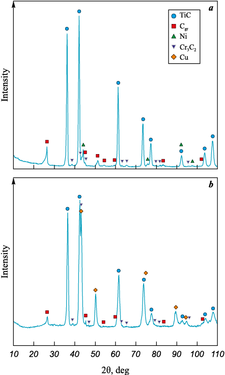
The results of XRD analysis for the synthesized compact materials are shown in Fig. 1 and Table 3. The samples contain titanium carbide with a lattice parameter significantly lower than the reference value for standard TiC powder (0.4315 nm) [38], which is attributed to the dissolution of chromium carbide into the TiC lattice. The phase composition also includes chromium carbide Cr3C2 and nickel (Ni) with dissolved Cr and Ti, as evidenced by peak shifts in the diffraction patterns. Unreacted graphite is also present – unlike carbon black, it does not fully dissolve in the melt over the course of the process due to slower dissolution kinetics. The excess carbon in the deposited coatings is expected to act as a solid lubricant, reducing the coefficient of friction. The presence of bronze in the X = 20 sample is confirmed by the appearance of Cu reflections in the diffraction pattern (Fig. 1, b). The absence of distinct Ni peaks is likely due to its dissolution in the bronze melt during the SHS process.
Fig. 1. XRD patterns of compact ceramics with X = 0 (a) and X = 20 (b) compositions
Table 3. Phase composition of compact ceramics of X = 0 and X = 20
| |||||||||||||||||||||||||||||||||||||||||||
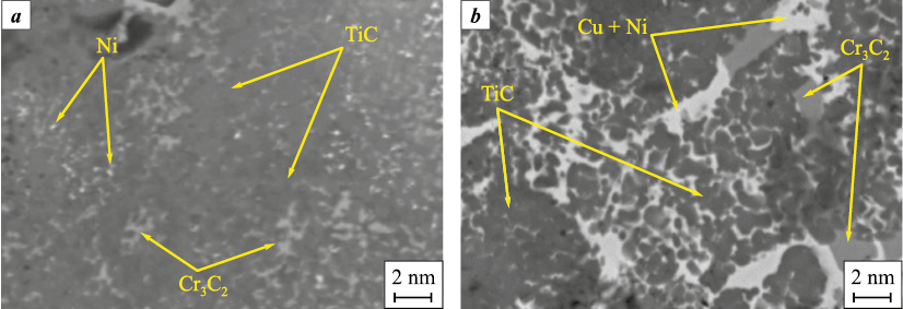
The SEM images of the cross-sections of synthesized ceramics with compositions X = 0 and X = 20 are shown in Fig. 2.
The microstructure of the X = 0 sample included TiC with dissolved Cr, chromium carbide Cr3C2 , nickel (Ni), and graphite. In the X = 20 sample, additional copper-rich layers were observed, with nickel dissolved in them without the formation of a distinct Ni phase. The average grain size of the primary carbide phase was approximately 3 µm.
Fig. 2. Microstructure of synthesized ceramics with compositions X = 0 (a) and X = 20 (b) |
Composition, structure, and properties of the coatings
Coating 1 consisted of (at. %): 22.2 Ti, 65.3 C, 10.2 Cr, and 2.3 Ni. Introducing nitrogen into the gas atmosphere (сoating 2) resulted in a nitrogen concentration increase from 0 to 26.3 at. %, accompanied by a reduction in carbon content to 45.7 at. % (Table 4). The concentrations of the remaining elements decreased by approximately 15–20 %. Coatings 3 and 4, which were alloyed with bronze, contained, in addition to the main elements, the following (at. %): 12.0 Cu, 0.4 Sn, and 0.3 P (сoating 3); and 9.6 Cu, 0.4 Sn, and 0.1 P (сoating 4).
Table 4. Elemental composition, thickness, and deposition rate of the coatings
| |||||||||||||||||||||||||||||||||||||||||||||||||||||||||||||||||||||||
It is important to note that energy-dispersive X-ray spectroscopy (EDS), while widely used for elemental analysis, is highly sensitive to surface topography and may produce inaccurate results for light elements such as C, N, and O. To obtain more reliable data, glow discharge optical emission spectroscopy (GDOES) was employed. This method allows accurate determination of both metallic and non-metallic elements [37].
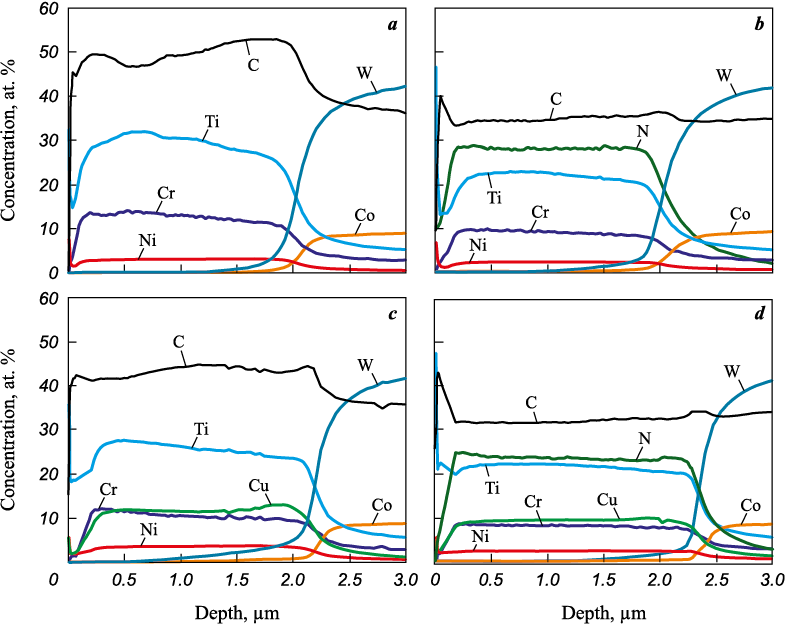
The GDOES analysis demonstrated that all elements are uniformly distributed across the coating thickness (Fig. 3).
Fig. 3. GDOES depth distribution profiles of coatings 1 (a), 2 (b), 3 (c), and 4 (d) |
A slight decrease in signal intensity was observed at the surface of the coatings, which may be attributed to surface contamination, the presence of adsorbed gases, and the formation of a natural oxide film. The gradual rise in substrate signal is due to increased surface roughness resulting from ion etching carried out prior to deposition. According to the GDOES results, the elemental composition of the coatings was as follows (at. %): 31.4 Ti, 52.1 C, 3.5 Ni, 13.0 Cr (coating 1); 23.0 Ti, 37.0 C, 2.5 Ni, 9.0 Cr, 28.5 N (coating 2); 27.5 Ti, 46.5 C, 3.8 Ni, 10.5 Cr, 11.7 Cu (coating 3); 22.8 Ti, 33.7 C, 2.7 Ni, 8.0 Cr, 9.4 Cu, 23.4 N (coating 4).
The atomic Ti/C ratio in the SHS targets was 0.48, while in the resulting coatings it increased to 0.59–0.68. This reduction in the carbon atom concentration in the coating, compared to that in the target is likely due to the higher scattering cross-section of carbon atoms compared to heavier titanium atoms in the plasma during deposition [39]. As shown below, the GDOES results are consistent with the XRD data.
The coating thicknesses determined from the GDOES profiles, along with the calculated deposition rates, are summarized in Table 4. For coatings 1 and 2 – deposited from SHS targets without bronze – the thickness and deposition rate were similar, measuring 2.0 µm and 91 nm/min, respectively. The use of bronze-containing targets resulted in a 10–15 % increase in both coating thickness and deposition rate. This effect can be attributed to the higher electrical conductivity (5.8·107 S/m) [40] and sputtering yield (3–6 atoms/ion) [41] of copper compared to titanium carbide (3.0·107 S/m and 0.5–1.0 atoms/ion) [42; 43]. It is worth noting that the reduction in deposition rate typically observed in reactive sputtering [44; 45] during transitions from conditions 1 → 2 and 3 → 4 was not observed in this study.
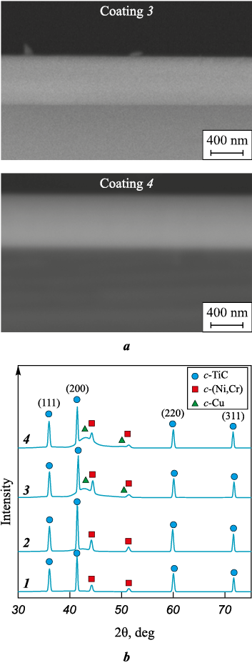
Typical SEM images of coating fracture surfaces are shown in Fig. 4, a. All coatings exhibited a dense, defect-free structure with no pronounced columnar features typically observed in TiC-based ion-plasma coatings [46; 47]. It is important to note that the presence of columnar grains in the structure generally has a detrimental effect on the mechanical and tribological properties of coatings [48].
Fig. 4. SEM images of cross-sectional fracture surfaces of coatings 3 and 4 (a), |
The diffraction patterns of the coatings are shown in Fig. 4, b. The main structural component of all coatings was the face-centered cubic (FCC) c-TiC phase (ICDD 31-1400). The crystallite size of this phase, calculated using the Scherrer equation for the most intense (200) reflection, was 36, 34, 32, and 29 nm for coatings 1 through 4, respectively. The lattice parameter (a) of the c-TiC phase ranged from 0.433 to 0.434 nm, which is consistent with the standard powder reference. Reflections at 2θ = 44.2° and 51.5° correspond to a solid solution of nickel and chromium, c-(Ni,Cr) (ICDD 77-7616). For coatings 1 and 2, the crystallite size of this phase was similar, falling within the range of 22–23 nm. The addition of bronze to both non-reactive and reactive coatings led to a reduction in the crystallite size of the c-(Ni,Cr) (111) phase to 15 nm in coating 3 and 8 nm in coating 4. In coatings 3 and 4, which were alloyed with bronze, an additional peak was detected at approximately 2θ ~ 43°, close to the position characteristic of copper (c-Cu, ICDD 04-0836). The pronounced peak broadening and the absence of other copper reflections suggest that copper is predominantly present in an amorphous state, forming intergranular layers that separate the crystallites of the primary phase and hinder their coalescence during growth [17–19].
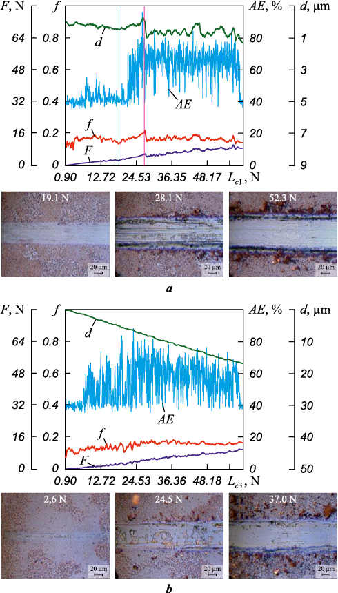
Scratch testing results are presented in Fig. 5, and the critical load values Lc1 and Lc2 are summarized in Table 5.
Fig. 5. Scratch testing results for coatings 1 (a) and 3 (b)
Table 5. Mechanical properties of coatings
|
Coating 1 demonstrated the highest critical loads, with Lc1 = 26.5 N and Lc2 > 60 N. For coating 2, the onset of cracking and the first spallation event – accompanied by fluctuations in acoustic emission and the coefficient of friction – occurred at a load of 15.7 N. Coating 3 exhibited the lowest crack resistance, with Lc1 = 2.6 N, although no spallation was observed over the entire load range. Coating 4 showed Lc1 = 19.9 N and Lc2 > 21 N. For all coatings, no indenter contact with the substrate was observed, indicating that the Lc3 value exceeded 60 N. Overall, coating 1 exhibited the best performance in terms of crack resistance and adhesion strength.
Nanoindentation tests revealed that the coatings had hardness values in the range of H = 18÷21 GPa and elastic moduli of E = 220÷235 GPa. The H/E ratio, which reflects the coating’s resistance to elastic strain to failure, and the H3/E2 ratio, indicative of resistance to plastic deformation, were calculated to assess potential tribological behavior [49; 50]. Coating 2 showed the highest values of H/E = 0.090 and H3/E2 = 0.174 GPa. Coatings 1, 3, and 4 displayed similar H/E values of 0.082–0.083 and H3/E2 values of 0.122–0.132 GPa. The relatively moderate hardness of the coatings may be attributed to the presence of an excess carbon-rich phase [4]. This is supported by atomic ratios of (Ti + Cr)/C = 0.82–0.85 for coatings 1 and 3 and (Ti + Cr)/(C + N) = 0.49–0.54 for coatings 2 and 4.
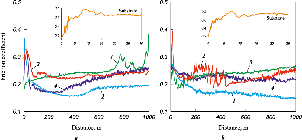
Tribological tests showed that the uncoated steel substrate exhibited the highest average coefficients of friction, favg = 0.63 and 0.71, in contact with SKH51 and SKD11 steel counter bodies, respectively (Fig. 6, Table. 6). Coating 1 had the lowest friction coefficient, f = 0.17÷0.18, likely due to its high carbon concentration (approximately 50 at. %). Coatings 2, 3, and 4 showed friction coefficients in the range of 0.22–0.25 with both counter body types. It is noteworthy that nitrogen alloying of coating 1 resulted in a 20 % increase in the coefficient of friction.
Fig. 6. Friction coefficient as a function of sliding distance
Table 6. Friction coefficient and specific wear rate
| ||||||||||||||||||||||||||||||||||||||||||||||||
An increase in the friction coefficient following nitrogen incorporation into TiC-based coatings was previously reported in [51] and was attributed to structural modification and a decrease in carbon content. Copper addition, in turn, led to a 40 % and 10 % increase in the friction coefficient of Ti–Cr–Ni–C and Ti–Cr–Ni–C–N coatings, respectively. A similar rise in the friction coefficient upon copper incorporation was observed earlier for TiCN and TiAlSiN coatings [52; 53]. The authors of those studies attributed this effect to the adverse impact of the brittle Cu2O phase that forms during sliding.
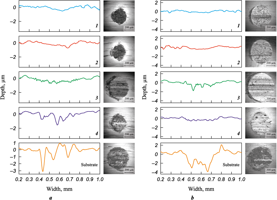
Fig. 7 shows two-dimensional wear track profiles and micrographs of the counter body surfaces after tribological tests of the coatings and substrate. The wear depth of the substrate exceeded that of the coatings by factors of 1.5–7.0 and 2.0–10.0 when using SKH51 and SKD11 counter bodies, respectively.
Fig. 7. Wear track profiles and micrographs counter body wear zones |
Wear track analysis revealed that the 40KhFA steel substrate exhibited a specific wear rate of 1.2·10–4 mm3/(N·m) (SKH51 counter body) and 2.7·10–4 mm3/(N·m) (SKD11 counter body) (Table 6).
Coatings 1 and 2 exhibited the lowest specific wear rates, with Vcoat = (1.3÷1.4)·10–6 mm3/(N·m) and (1.1÷1.2)·10–6 mm3/(N·m) in tribological pairs with SKH51 and SKD11, respectively. Coatings 3 and 4 showed higher wear rates when paired with SKH51 counterbodies – Vcoat = 5.0·10–6 and 2.3·10–6 mm3/(N·m) – and comparable Vcoat = (3.6÷3.7)·10–6 mm3/(N·m) when tested against SKD11. The reduced wear resistance of the coatings upon bronze addition may be attributed to the fact that copper, the primary component, is a soft phase more prone to abrasion [54]. Microscopic analysis of wear scars on the counterbodies (Fig. 7) revealed that the greatest wear occurred during contact with the uncoated substrate (Table 6). The minimum counterbody wear (Vball ) for the SKH51 ball was observed with coatings 1 and 2, while for the SKD11 ball it was recorded with coatings 1 and 4.
Thus, deposition of Ti–Cr–Ni–C–(N) and Ti–Cr–Ni–Cu–Sn–P–C–(N) coatings led to a 2.5–4.2-fold reduction in the friction coefficient of the steel substrate and a two-order-of-magnitude decrease in specific wear. Notably, coating 1 demonstrated the most favorable combination of low friction coefficient and high wear resistance in tests with both SKH51 and SKD11 balls, while also exhibiting the highest crack resistance and adhesion strength.
Conclusion
Ti–Cr–Ni–C–(N) and Ti–Cr–Ni–Cu–Sn–P–C–(N) coatings were deposited by magnetron sputtering in Ar and Ar–N2 atmospheres using SHS-derived targets. The coatings exhibited dense, defect-free, and uniform microstructures. The primary structural components in all coatings were FCC phases c-TiC(N) and c-(Ni,Cr). For the Ti–Cr–Ni–C and Ti–Cr–Ni–C–N coatings, the crystallite sizes of the c-TiC(N) and c-(Ni,Cr) phases were similar, ranging from 34–36 nm and 22–23 nm, respectively. The introduction of bronze resulted in the formation of an amorphous Cu-based phase and a reduction in the crystallite size of c-TiC by 12–15 % and c-(Ni,Cr) by 32–64 %. All coatings demonstrated hardness values in the range of 18–21 GPa and elastic moduli between 220 and 235 GPa. The Ti–Cr–Ni–C coating exhibited the best combination of crack resistance, adhesion strength, lowest coefficient of friction (0.17–0.18), and high wear resistance (1.4·10–6 and 1.2·10–6 mm3/(N·m) when paired with SKH51 and SKD11 counterbodies, respectively). Deposition of Ti–Cr–Ni–Cu–Sn–P–C–N coatings contributed to a 2.5–4.2-fold reduction in the substrate’s coefficient of friction and a two-order-of-magnitude decrease in specific wear.
References
1. Larhlimi H., Ghailane A., Makha M., Alami J. Magnetron sputtered titanium carbide-based coatings: A review of science and technology. Vacuum. 2022;197:110853. https://doi.org/10.1016/j.vacuum.2021.110853
2. He J., He Z., Qin Y., Zhao H., Bi Y. A review of TiCN coating prepared by reaction plasma spraying. Journal of Thermal Spray Technology. 2022;31(8):2280–2299. https://doi.org/10.1007/s11666-022-01454-5
3. Aramian A., Sadeghian Z., Narimani M., Razavi N., Berto F. A review on the microstructure and properties of TiC and Ti(C,N) based cermets. International Journal of Refractory Metals and Hard Materials. 2023;115:106320. https://doi.org/10.1016/j.ijrmhm.2023.106320
4. Martínez-Martínez D., López-Cartes C., Justo A., Fernández A., Sánchez-López J.C. Self-lubricating Ti–C–N nanocomposite coatings prepared by double magnetron sputtering. Solid State Sciences. 2009;11(2):660–670. https://doi.org/10.1016/j.solidstatesciences.2008.09.004
5. Chen Q., Liang D., Zhang E., Yang L., Zhou Q., Huang B., Han S. Influence of C2H2/N2 flow ratio on the microstructure, mechanical properties, and electrochemical behavior of TiCN composite coatings. Vacuum. 2023;216:112349. https://doi.org/10.1016/j.vacuum.2023.112349
6. Karlsson L., Hultman L., Johansson M.P., Sundgren J.-E., Ljungcrantz H. Growth, microstructure, and mechanical properties of arc evaporated TiCxN1−x (0 ≤ x ≤ 1) films. Surface and Coatings Technology. 2000;126(1):1–14. https://doi.org/10.1016/S0257-8972(00)00518-1
7. Podhurska V., Kuprin O., Prikhna T., Ostash O., Pohl D., Karpets M., Sverdun V., Serbeniuk T., Chepil R., Potapov P., Ponomarov S. Development of oxidation-resistant and electrically conductive coating of Ti–Al–C system for the lightweight interconnects of solid oxide fuel cells. Heliyon. 2024;10(1):e23275. https://doi.org/10.1016/j.heliyon.2023.e23275
8. Zhang X., Qiu Y., Tan Z., Lin J., Xu A., Zeng Y., Moore J.J., Jiang J. Effect of Al content on structure and properties of TiAlCN coatings prepared by magnetron sputtering. Journal of Alloys and Compounds. 2014;617:81–85. https://doi.org/10.1016/j.jallcom.2014.08.009
9. Testa V., Morelli S., Bolelli G., Bosi F., Puddu P., Colella A., Manfredini T., Lusvarghi L. Corrosion and wear performances of alternative TiC-based thermal spray coatings. Surface and Coatings Technology. 2022;438:128400. https://doi.org/10.1016/j.surfcoat.2022.128400
10. Zhang S., Fu Y., Du H., Zeng X.T., Liu Y.C. Magnetron sputtering of nanocomposite (Ti,Cr)CN/DLC coatings. Surface and Coatings Technology. 2003;162(1):42–48. https://doi.org/10.1016/S0257-8972(02)00561-3
11. Kiryukhantsev-Korneev Ph.V., Sheveyko A.N., Shvindina N.V., Levashov E.A., Shtansky D.V. Comparative study of Ti–C–Ni–Al, Ti–C–Ni–Fe, and Ti–C–Ni–Al/Ti–C–Ni–Fe coatings produced by magnetron sputtering, electro-spark deposition, and a combined two-step process. Ceramics International. 2018;44(6):7637–7646. https://doi.org/10.1016/j.ceramint.2018.01.091
12. Bondarev A.V., Kiryukhantsev-Korneev Ph.V., Levashov E.A., Shtansky D.V. Tribological behavior and self-healing functionality of TiNbCN–Ag coatings in wide temperature range. Applied Surface Science. 2017;396: 110–120. https://doi.org/10.1016/j.apsusc.2016.10.188
13. Ghorbani M., Mazaheri M., Afshar A. Wear and friction characteristics of electrodeposited graphite–bronze composite coatings. Surface and Coatings Technology. 2005;190(1):32–38. https://doi.org/10.1016/j.surfcoat.2004.04.092
14. Ghorbani M., Mazaheri M., Khangholi K., Kharazi Y. Electrodeposition of graphite-brass composite coatings and characterization of the tribological properties. Surface and Coatings Technology. 2001;148(1):71–76. https://doi.org/10.1016/S0257-8972(01)01322-6
15. Musil J., Louda M., Soukup Z., Kubásek M. Relationship between mechanical properties and coefficient of friction of sputtered a-C/Cu composite thin films. Diamond and Related Materials. 2008;17(11):1905–1911. https://doi.org/10.1016/j.diamond.2008.04.009
16. Shao F., Zhao H., Ni J., Zhuang Y., Sheng J., Yang J., Zhong X., Tao S. Corrosion behavior and mechanical properties of plasma sprayed Al2O3-aluminum bronze and Ca2SiO4-aluminum bronze coatings. Materials Chemistry and Physics. 2024;311:128579. https://doi.org/10.1016/j.matchemphys.2023.128579
17. Musil J. Hard and superhard nanocomposite coatings. Surface and Coatings Technology. 2000;125(1–3):322–330. https://doi.org/10.1016/S0257-8972(99)00586-1
18. Musil J., Kadlec S., Vyskočil J., Valvoda V. New results in d.c. reactive magnetron deposition of TiNx films. Thin Solid Films. 1988;167(1–2):107–120. https://doi.org/10.1016/0040-6090(88)90487-7
19. Soldán J., Musil J. Structure and mechanical properties of DC magnetron sputtered TiC/Cu film. Vacuum. 2006;81(4):531–538. https://doi.org/10.1016/j.vacuum.2006.07.013
20. Sun H., Billard A., Luo H., Zheng W.-T., Zheng X.-L., Dai M.-J., Lin S.-S., Shi Q., Sanchette F. Influence of carbon content on the mechanical properties of TiCN–Cu nanocomposite coatings prepared by multi-arc ion plating. Vacuum. 2021;187:110139. https://doi.org/10.1016/j.vacuum.2021.110139
21. Ghahabi E., Shajari Y., Razavi M., Mobasherpour I., Tayebi Fard S.A. Effect of iron content on the wear behavior and adhesion strength of TiC–Fe nanocomposite coatings on low carbon steel produced by air plasma spray. Ceramics International. 2020;46(3):2670–2676. https://doi.org/10.1016/j.ceramint.2019.09.255
22. Das A.K., Kumar R. Investigation on wear behaviour of TiC/Co/Y2O3 metal matrix composite coating developed on AZ91D Mg alloy by plasma transferred arc cladding process. Materials Letters. 2024;355:135457. https://doi.org/10.1016/j.matlet.2023.135457
23. Sun L., Wang X., Cao Y., Wang Y., Ma Q., Wu H., Hua K., Wang H. High-temperature fretting wear behavior and microstructure stability of a laser-cladding Ti–Al–C–N composite coating meditated by variable cycle conditions. Tribology International. 2025;201:110224. https://doi.org/10.1016/j.triboint.2024.110224
24. Gvetadze R., Arutyunov S., Kryuchkov S., Antipov M., Bazhin, P., Mustafaev M., Deshev A., Tsarev V., Andreev M., Katkov I., Agasieva S., Avdeeva V. Cermet coatings obtained by electric spark alloying to increase service life of dental instruments. Ceramics International. 2024;50(24, Part A):52613–52621. https://doi.org/10.1016/j.ceramint.2024.10.112
25. Kuptsov K.A., Sheveyko A.N., Sidorenko D.A., Shtansky D.V. Electro-spark deposition in vacuum using graphite electrode at different electrode polarities: Peculiarities of microstructure, electrochemical and tribological properties. Applied Surface Science. 2021;566:150722. https://doi.org/10.1016/j.apsusc.2021.150722
26. Gassner M., Schalk N., Tkadletz M., Czettl C., Mitterer C. Thermal crack network on CVD TiCN/α-Al2O3 coated cemented carbide cutting tools. International Journal of Refractory Metals and Hard Materials. 2019;81:1–6. https://doi.org/10.1016/j.ijrmhm.2019.02.006
27. Kiryukhantsev-Korneev P., Sytchenko A., Sheveyko A., Moskovskikh D., Vorotylo S. Two-layer nanocomposite TiC-based coatings produced by a combination of pulsed cathodic arc evaporation and vacuum electro-spark alloying. Materials. 2020;13(3):547. https://doi.org/10.3390/ma13030547
28. Sajjadi S.A., Saba F., Ghadirzadeh A., Di Fonzo F. Synthesis of TiC coating on Ti substrate using pulsed laser deposition and mechanical milling techniques along with statistical modeling of the process by response surface methodology. Powder Technology. 2017;305:704–713. https://doi.org/10.1016/j.powtec.2016.10.054
29. Kelly P.J., Arnell R.D. Magnetron sputtering: A review of recent developments and applications. Vacuum. 2000;56(3):159–172. https://doi.org/10.1016/S0042-207X(99)00189-X
30. Shtansky D.V., Gloushankova N.A., Sheveiko A.N., Kiryukhantsev-Korneev Ph.V., Bashkova I.A., Mavrin B.N., Ignatov S.G., Filippovich S.Yu., Rojas C. Si-doped multifunctional bioactive nanostructured films. Surface and Coatings Technology. 2010;205(3):728–739. https://doi.org/10.1016/j.surfcoat.2010.07.063
31. Shtansky D.V., Kiryukhantsev-Korneev Ph.V., Sheveyko A.N., Kutyrev A.E., Levashov E.A. Hard tribological Ti–Cr–B–N coatings with enhanced thermal stability, corrosion- and oxidation resistance. Surface and Coatings Technology. 2007;202(4–7):861–865. https://doi.org/10.1016/j.surfcoat.2007.05.064
32. Kiryukhantsev-Korneev Ph.V., Chertova A.D., Chudarin F.I., Patsera E.I., Levashov E.A. The structure and properties of high-entropy (MoTaNbZrHf)–Si–B coatings deposited by DCMS and HIPIMS methods using the multilayer target. Surface and Coatings Technology. 2024;484:130797. https://doi.org/10.1016/j.surfcoat.2024.130797
33. Levashov E.A., Mukasyan A.S., Rogachev A.S., Shtansky D.V. Self-propagating high-temperature synthesis: An overview of recent developments. International Materials Reviews. 2017;62(4):203–239. https://doi.org/10.1080/09506608.2016.1243291
34. Levashov E.A., Malochkin O.V., Kudryashov A.E., Glukhov S.A., Sviridova T.A., Gammel F., Zukhentrunk R. On features of the effect of nanocrystalline powders on burning processes and forming composition, structure, and properties of STIM-3B alloy. Izvestiya. Non-Ferrous Metallurgy. 2001;(1):53–59. (In Russ.).
35. Shiryaev A.A. Thermodynamics of SHS: Modern approach. International Journal of Self-Propagating High-Temperature Synthesis. 1995;4(4):351–362.
36. Kiryukhantsev-Korneev Ph.V., Sytchenko A.D., Sviridova T.A., Sidorenko D.A., Andreev N.V., Klechkovskaya V.V., Polčak J., Levashov E.A. Effects of doping with Zr and Hf on the structure and properties of Mo–Si–B coatings obtained by magnetron sputtering of composite targets. Surface and Coatings Technology. 2022;442:128141. https://doi.org/10.1016/j.surfcoat.2022.128141
37. Kiryukhantsev-Korneev F.V. Possibilities of glow discharge optical emission spectroscopy in the investigation of coatings. Russian Journal of Non-Ferrous Metals. 2014;55:494–504. https://doi.org/10.3103/S1067821214050126
38. Zueva L.V., Gusev A.I. Effect of nonstoichiometry and ordering on the period of the basis structure of cubic titanium carbide. Physics of the Solid State. 1999;41(7):1032–1038. https://doi.org/10.1134/1.1130931
39. Brydson R., Hondow N. Electron energy loss spectrometry and energy dispersive X-ray analysis. In: Aberration-corrected analytical transmission electron microscopy. Eds. S. Brooks, R. Brydson. Wiley, 2011. P. 163–210. https://doi.org/10.1002/9781119978848.ch7
40. Davis J.R. Copper and copper alloys. ASM International, 2001. 652 p.
41. Semenov A.P., Semenova I.A., Tsyrenov D.B-D., Nikolaev E.O. Physical sputtering of a copper anode of a planar magnetron by a beam of accelerated argon ions with an energy of 1–10 keV. Instruments and Experimental Techniques. 2021;(64):539–541. https://doi.org/10.1134/S0020441221040242
42. Mhadhbi M., Driss M. Titanium carbide: synthesis, properties and applications. Journal of Brilliant Engineering. 2021;2:1–11. https://doi.org/10.36937/ben.2021.002.001
43. Kovtun Yu.V., Kuprin A.S., Podhurska V.Ya. Sputtering yields of TiC and MAX phase Ti2AlC using Ne, Ar, Xe ions. Nuclear Instruments and Methods in Physics Research. Section B: Beam Interactions with Materials and Atoms. 2024;554:165433. https://doi.org/10.1016/j.nimb.2024.165433
44. Kiryukhantsev-Korneev Ph.V., Sytchenko A.D., Kozlova N.S., Zabelina E.V., Sidorenko D.A., Levashov E.A., Feng P. Effect of nitrogen on the structure and properties of Zr–Si–B–N coatings deposited by magnetron sputtering. Surface and Coatings Technology. 2023;474:130042. https://doi.org/10.1016/j.surfcoat.2023.130042
45. Hahn R., Tymoszuk A., Wojcik T., Kirnbauer A., Kozák T., Čapek J., Sauer M., Foelske A., Hunold O., Polcik P., Mayrhofer P.H., Riedl H. Phase formation and mechanical properties of reactively and non-reactively sputtered Ti–B–N hard coatings. Surface and Coatings Technology. 2021;420:127327. https://doi.org/10.1016/j.surfcoat.2021.127327
46. Lauridsen J., Nedfors N., Jansson U., Jensen J., Eklund P., Hultman L. Ti–B–C nanocomposite coatings deposited by magnetron sputtering. Applied Surface Science. 2012; 258(24):9907–9912. https://doi.org/10.1016/j.apsusc.2012.06.049
47. Larhlimi H., Ghailane A., Makha M., Alami J. Magnetron sputtered titanium carbide-based coatings: A review of science and technology. Vacuum. 2022;197:110853. https://doi.org/10.1016/j.vacuum.2021.110853
48. Sytchenko A.D., Kozlova N.S., Zabelina E.V., Loginov P.A., Levashov E.A., Kiryukhantsev-Korneev Ph.V. The effect of the Ar/N2 gas ratio on the structure and properties of Ta–Si–N coatings produced by magnetron sputtering of a TaSi2 target. Surface and Interfaces. 2023;37:102654. https://doi.org/10.1016/j.surfin.2023.102654
49. Beake B.D. The influence of the H/E ratio on wear resistance of coating systems – insights from small-scale testing. Surface and Coatings Technology. 2022;442:128272. https://doi.org/10.1016/j.surfcoat.2022.128272
50. Leyland A., Matthews A. On the significance of the H/E ratio in wear control: A nanocomposite coating approach to optimised tribological behaviour. Wear. 2000;246:1–11. https://doi.org/10.1016/S0043-1648(00)00488-9
51. Musil J., Hromadka M., Novak P. Effect of nitrogen on tribological properties of amorphous carbon films alloyed with titanium. Surface and Coatings Technology. 2011;205(S2):S84–S88. https://doi.org/10.1016/j.surfcoat.2010.12.048
52. Zhao H., Guo F., Zhu L., He J., Yin F. The effect of Cu addition on the crystallization behavior and tribological properties of reactive plasma sprayed TiCN–Cu coatings. Ceramics International. 2020;46(6):8344–8351. https://doi.org/10.1016/j.ceramint.2019.12.066
53. Heo S.B., Kim W.-R., Kim J.H., Choe S., Kim D.W., Lim J.-H., Park I.-W. Effects of copper content on the microstructural, mechanical and tribological properties of TiAlSiN–Cu superhard nanocomposite coatings. Coatings. 2022;12(12):1995. https://doi.org/10.3390/coatings12121995
54. Li F., Dai W., Wu Z., Xu Y., Wang J., Wang Q. Effect of Cu content on the mechanical and tribological properties of MoN–Cu coatings deposited by HiPIMS. Surface and Coatings Technology. 2025;497:131769. ttps://doi.org/10.1016/j.surfcoat.2025.131769
About the Authors
Ph. V. Kiryukhantsev-KorneevRussian Federation
Philipp V. Kiryukhantsev-Korneev – Dr. Sci. (Eng.), Professor of the Department of Powder Metallurgy and Functional Coatings (PM&FC) of National University of Science and Technology “MISIS” (NUST MISIS), Head of the Laboratory "In situ Diagnostics of Structural Transformations” of Scientific-Educational Center of Self-Propagating High-Temperature Synthesis MISIS–ISMAN (SHS-Center)
1 Bld, 4 Leninskiy Prosp, Moscow 119049, Russia
A. D. Chertova
Russian Federation
Alina D. Chertova – Cand. Sci. (Eng.), Research Scientist of SHS-Center MISIS–ISMAN
1 Bld, 4 Leninskiy Prosp, Moscow 119049, Russia
Yu. S. Pogozhev
Russian Federation
Yuri S. Pogozhev – Cand. Sci. (Eng.), Senior Research Scientist of SHS-Center MISIS–ISMAN
1 Bld, 4 Leninskiy Prosp, Moscow 119049, Russia
E. A. Levashov
Russian Federation
Evgeniy A. Levashov – Dr. Sci. (Eng.), Prof., Corresponding Member of the RAS, Head of the Department of PM&FC of NUST MISIS, Director of SHS-Center MISIS–ISMAN
1 Bld, 4 Leninskiy Prosp, Moscow 119049, Russia
Review
For citations:
Kiryukhantsev-Korneev P.V., Chertova A.D., Pogozhev Yu.S., Levashov E.A. Structure and properties of antifriction Ti–Cr–Ni–Cu–Sn–P–C–N coatings deposited by magnetron sputtering of composite SHS targets. Powder Metallurgy аnd Functional Coatings (Izvestiya Vuzov. Poroshkovaya Metallurgiya i Funktsional'nye Pokrytiya). 2025;19(3):60-73. https://doi.org/10.17073/1997-308X-2025-3-60-73
JATS XML


