Scroll to:
Combined technology of electrospark and cathodic-arc formation of wear- and oxidation resistant coatings
https://doi.org/10.17073/1997-308X-2025-4-60-76
Abstract
The regularities of formation of wear- and oxidation-resistant coating under combined electrospark and cathodic-arc treatment (ESCAT) of AZhK superalloy were studied. The effect of electrode polarity and rare-earth (Ce, Er) microalloying of Al–Ca-based rod electrodes on the structure, strengthening and oxidation resistance of the deposited coatings was studied. It was found that anodic polarity secures the formation of crack-free coatings predominantly composed of γ′-Ni3Al intermetallic (L12-type structure, 3.600 Å). These coatings reached a thickness of 15–20 μm due to the oriented growth of crystallites with a transverse size below 300 nm. In contrast, the coatings formed at cathodic polarity have consisted of two intermetallic phases: β-NiAl (B2 structure, 2.895 Å) and γ′-Ni3Al (L12 , 3.595 Å). Structural and phase transformations occurring during the treatment of a AZhK substrate (initial hardness of 5.2 GPa) using electrodes of different polarities constitute the dominant strengthening factors. The maximum hardness (12.3 GPa) was recorded for coatings composed of β-NiAl and γ′-Ni3Al phases. Coatings obtained with anodic electrode polarity exhibited relatively lower hardness values (7.3 GPa) accompanied by low elastic modulus values (112 GPa). The wear rate of these coatings ranged from 6 to 7.5·10–5 mm3/(N·m), representing a sixfold improvement of wear resistance compared to the untreated AZhK alloy. In-situ TEM studies revealed excellent thermal stability of the γ′-Ni3Al intermetallic structure upon heating the coating lamellae cut of the coating obtained under anodic polarity up to 700 °C. Results of high-temperature oxidation tests at 1000 °C indicate that the coating the AZhK alloy change the oxidation law from linear to logarithmic one. The minimum thickness of the oxide layer (about 3 μm) was found in the coatings obtained by ESCAT using Al–Ca–Er electrode with anodic polarity. That is 10 times less than the thickness of the oxide layer of AZhK alloy. The change of oxidation law during annealing to the logarithmic one is due to in-situ formed the NiAl2O4/α-Al2O3 barrier layer strengthened with CaMoO4 particles. It slowing down of oxygen diffusion in bulk of substrate providing its excellent oxidation resistance.
Keywords
For citations:
Mukanov S.K., Petrzhik M.I., Kudryashov A.E., Loginov P.A., Shvyndina N.V., Sheveyko A.N., Kuptsov K.A., Levashov E.A. Combined technology of electrospark and cathodic-arc formation of wear- and oxidation resistant coatings. Powder Metallurgy аnd Functional Coatings (Izvestiya Vuzov. Poroshkovaya Metallurgiya i Funktsional'nye Pokrytiya). 2025;19(4):60-76. https://doi.org/10.17073/1997-308X-2025-4-60-76
Introduction
Over the past decades, considerable attention has been devoted to developing methods for extending the service life of superalloys used in high-temperature applications [1; 2], which are essential for the advancement of aerospace, chemical, and power engineering. One of the key limitations of superalloys in the manufacture of critical components is their insufficient wear and oxidation resistance, necessitating the development of effective surface modification techniques [3].
Electrospark treatment (EST) is a promising technology for strengthening and restoring working surfaces, as well as for producing coatings with enhanced wear and oxidation resistance [4–6]. An important advantage of EST is its localized action of electrical discharges, which makes it possible to treat specific areas of critical components without overheating. A distinctive feature of the technology is the need for careful selection and control of processing modes to ensure the formation of crack-free coatings.
The versatility of EST is determined by the wide range of developed electrode compositions, which allows selecting specific alloys to improve surface-sensitive properties of components. In particular, the use of fusible electrodes Al–Si, Al–Ca–Si, and Al–Ca–Mn in [7; 8] or EST of EP741NP alloy samples fabricated by selective laser melting (SLM) resulted in the formation of coatings containing intermetallic NixAly particles synthesized during EST. This not only increased wear resistance by a factor of 4.5 through intermetallic strengthening but also reduced surface roughness to Ra = 3 µm due to the healing of surface defects typical of SLM. In addition, the in-situ synthesis of (Al, Ca)O nanoparticles during oxidative annealing of the coatings at 1000 °C provided a fourfold increase in oxidation resistance of the EP741NP alloy [8]. The oxidation rate can be further reduced [9] by improving the crack resistance and adhesion of the oxide layer to the substrate through microalloying the coatings with rare-earth (RE) metals. In this context, particular interest lies in studying the effect of Al–Ca–RE electrodes, where RE = Ce or Er. Such additives are especially relevant for coatings applied to superalloys in order to extend their operating temperature range.
A promising approach is to combine, within a single technological cycle, electrospark and cathodic-arc treatment (ESCAT) [10]. The clear advantages of computer-controlled combined processing include improved reproducibility of the technology and intensified mass transfer during cathodic arc evaporation of the electrode.
The aim of this study was to investigate the conditions for forming wear- and oxidation-resistant coatings by combining electrospark and cathodic-arc treatment (ESCAT) of the AZhK superalloy.
Methods
Rod electrodes 4 mm in diameter, made of near-eutectic Al–Ca–Ce and Al–Ca–Er alloys prepared in accordance with TU 24.45.30–042–11301236–2024, were used for the combined process of ESCAT. The electrodes were produced by a two-stage process: (1) remelting of the charge components into an ingot in a resistance furnace; (2) induction melting of the ingot followed by casting of the melt into a copper mold in a vacuum chamber filled with argon at a pressure of 0.2 atm.
Substrates were made of the AZhK nickel-based superalloy, fabricated by selective laser melting (SLM) at JSC Komposit (Russia). The chemical composition of the AZhK alloy substrates is given below [11], wt. %:
|
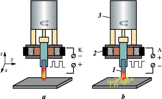
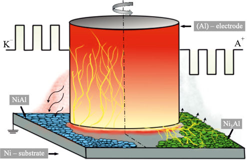
ESCAT were carried out in a single cycle using a modified cap-type UVN-2M unit (Russia), equipped with a CNC system for programmed lateral movement of the sample during processing under specified conditions. After reaching forevacuum, the vacuum chamber was filled with argon to a pressure of 20 Pa, in accordance with TI 65–11301236–2024. This pressure ensures the simultaneous initiation of an arc discharge and electrospark discharges [10]. A schematic of the ESCAT process is shown in Fig. 1.
Fig. 1. Schematic diagram of the automated ESCAT setup |
The microstructure and composition of the samples were examined using a Hitachi S-3400N scanning electron microscope equipped with a NORAN System 7 X-ray microanalysis system (Thermo Scientific, USA). For detailed microstructural studies, cross-sectional samples were prepared using standard metallographic methods (grinding, polishing), followed by electrochemical etching at a constant voltage of 10 V in an aqueous 10 % H2SO4 solution.
X-ray diffraction (XRD) phase analysis was performed using diffractograms obtained on a DRON-4 diffractometer (Burevestnik, Russia) with monochromatic CuKα radiation (1.5418 Å), and in the case of oxide layers, CoKα radiation (1.7902 Å), in the 2θ range of 20–110°. For detailed analysis of coating substructures, a JEM-2100 transmission electron microscope (Jeol, Japan) equipped with an Oxford Instruments X-Max 80 energy-dispersive detector was employed. Lamellae were cut from the coating surface layer using a focused ion beam system (Quanta 200 3D FIB, FEI Company, USA). TEM foils were additionally thinned by ion etching on a PIPS II system (Gatan, Inc., USA). In-situ studies of structural–phase transformations in the coatings under thermal exposure at 400, 600, and 700 °C were carried out directly in the microscope column. The heating rate was 50 °C/min. Bright-field images and electron diffraction patterns were obtained with a dwell time of about 15 min at each heating step.
Mechanical properties (hardness H and elastic modulus E) of the coatings were measured on cross-sectional samples using a Nano-Hardness Tester (CSM Instruments, Switzerland) at a maximum load of 10 mN. Tribological tests were performed on a CSM Tribometer (Switzerland) in accordance with ASTM G133-22 under reciprocating sliding at room temperature in air. A 3-mm diameter 100Cr6 steel ball (analog of ShKh15) was used as the stationary counterbody. The test parameters were: track length – 4 mm, applied load – 2 N, maximum speed – 5 cm/s. Wear tracks were examined using a WYKO NT1100 optical profilometer (Veeco, USA).
Oxidation resistance tests at high temperature were carried out under cyclic heating–cooling in a SNOL 7.2/1200 muffle furnace (Lithuania), exposing the samples in air at 1000 °C. The total isothermal holding time in air was 30 h. After each cycle of “heating – isothermal hold – cooling”, the samples were weighed on an ALC-210d4 analytical balance (Acculab, USA) with an accuracy of 10–5 g. The specific mass gain (K) was calculated as:
K = ∆m/S0 ,
where ∆m is the mass difference before and after oxidation, mg; S0 is the total surface area of the sample before testing, cm2.
Results
Structure of fusible
Al–Ca–RE (Ce, Er) electrodes
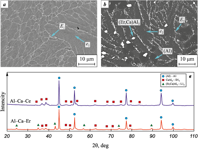
Figs. 2, a and b show the microstructures of the fusible electrodes, while the diffraction spectrum (Fig. 2, c) displays the lines corresponding to their phase constituents. It can be seen that the Al–Ca–Ce electrodes have a near-eutectic structure, which is consistent with the results of [12]. As shown in Table 1, this structure consists of fine two-phase eutectics e1 [(Al) + CaAl4 ] and three-phase eutectics E1 [(Al) + CaAl4 + (Ca,Ce)Al4 ], as well as dendrites of a solid solution based on aluminum (Al).
Fig. 2. SEM backscattered electron images of the microstructure of Al–Ca–Ce (a)
Table 1. Elemental distribution across structural constituents
| ||||||||||||||||||||||||||||||||||||||||||
As shown in Fig. 2, b, the addition of Er to the Al–Ca–Er electrode promotes the formation of bright, faceted primary Al3(Er,Ca) crystals. Consequently, the principal structural constituents of the Al–Ca–Er electrode are fine two-phase eutectics [(Al) + CaAl4 ], three-phase eutectics [(Al) + CaAl4 + (Er,Ca)Al3 ], primary Al3(Er,Ca) crystals, and (Al) dendrites. The elemental distribution among the structural constituents of the Al–Ca–Ce and Al–Ca–Er electrodes is summarized in Table 1.
Kinetics of coating formation
and structure
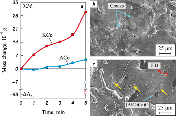
The kinetic curves of mass transfer as a function of electrode polarity are shown in Fig. 3. The maximum specific mass gain of the substrate, corresponding to the greatest coating thickness, is observed after 5 min of treatment, regardless of electrode polarity. However, the specific erosion after 5 min of treatment under cathodic electrode connection (ΔА5 = −94.9·10−4 g) is an order of magnitude higher than that under anodic polarity (ΔА5 = −7.1·10−4 g). The mass gain curve obtained under anodic polarity (ACe) indicates a low contribution of mass transfer (ΔK5 = 4.8·10−4 g). In this case, an increase in mass is observed only after 3 min of treatment.
Fig. 3. Kinetic curves of mass transfer for the Al–Ca–Ce electrode during ESCAT |
On the surface of the ACe series coatings, elongated solidified droplets can be observed (Fig. 3, c), some of which are marked with yellow arrows. Their formation under anodic polarity can be attributed to local melting of fusible structural constituents within cathode spot [12]. In addition, oxide particles approximately 15 µm in size were found on the surface of these coatings (highlighted with orange arrows). According to EDS data, these particles, in addition to oxygen, contain high concentrations of Al (28–33 at. %) and Ca (6–10 at. %). They also contain about 1 at. % Ce and Er, which is expected given their high affinity for oxygen. Under cathodic polarity, the surfaces of the coatings (KEr and KCe) exhibit overlapping solidified melt droplets, but they are less homogeneous in composition. It is worth noting that, unlike the A-series, cracks were observed on the surfaces of the K-series coatings.
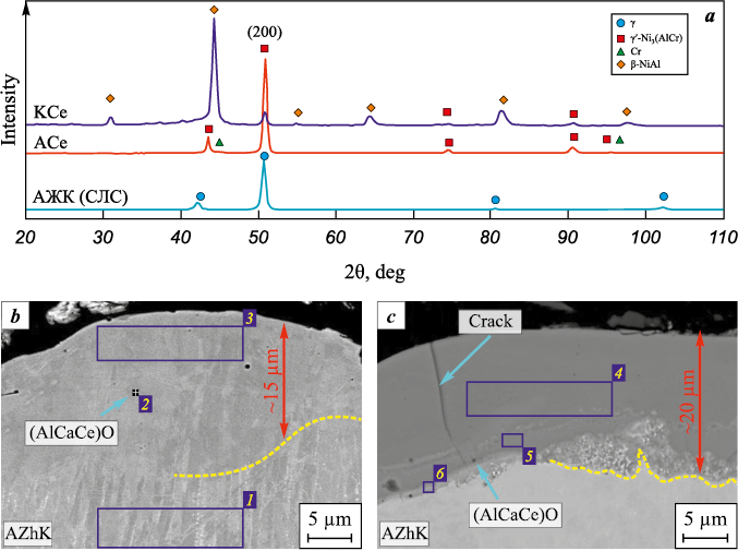
XRD patterns (Fig. 4, a) of the initial and ESCAT -treated substrates revealed differences in the phase composition of the coatings depending on electrode polarity. Under cathodic polarity (sample KCe), the coating consists of β-NiAl, which has an ordered cubic B2 crystal structure, and γ′-Ni3(AlCr) with an ordered L12 superstructure. The β-phase fraction is dominant (Table 2), amounting to 84.6 wt. %.
Fig. 4. Diffraction patterns of the initial AZhK alloy and after ESCAT with an Al–Ca–Ce electrode (a),
Table 2. Phase composition of the AZhK alloy – initial and after ESCAT
|
Anodic polarity (sample ACe) results in the formation of a coating predominantly composed of γ′-Ni3(AlCr) (97.6 wt. %). Diffraction peaks of the β-phase were not detected in the diffractogram. This indicates an insufficient amount of free Al in the EST melt to form the equiatomic NiAl intermetallic.
As shown in Figs. 4, b and c, typical cross-sectional images of the coatings are presented. The ACe and AEr coatings do not display a distinct interface with the substrate, which can be attributed to their similar elemental concentrations (Table 3). According to EDS data (regions 1 and 3), however, the Al content in the coatings (15 at. %) is nearly twice that of the AZhK alloy (9 at. %). No Ca was detected in the bulk of the coating, and the Ce content did not exceed 0.2 at. %. The coating structure nevertheless contains small black inclusions identified by EDS as (AlCaCe)O (Table 3, region 2). Larger particles of the same composition were also found on the surfaces of these coatings (see Fig. 3, c).
Table 3. EDS results for coating regions ACe and KCe shown in Fig. 4
| |||||||||||||||||||||||||||||||||||||||||||||||||||||||||||||||||||||||||||||||||||||||
The thickness of the coatings formed under cathodic polarity (18–20 µm) is greater than that of the anodic ACe and AEr coatings (15 µm). The microstructure of the cathodic coatings (Fig. 4, c) exhibits pronounced differences due to the increased incorporation of elements from the Al–Ca–RE electrodes. As shown in Table 3, the Al concentration in the K-series coatings reaches 74 at. %, while the Ni content decreases to 15 at. %. A distinct interface between the AZhK substrate and the coatings is evident; it is heterogeneous in both structure and composition, with the Ni concentration in this region at about 30 at. %. It should also be noted that under cathodic polarity, Ca and RE metals are distributed more uniformly throughout the coatings compared with the ACe and AEr samples, although the total RE metal content does not exceed 0.6 at. %.
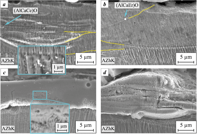
The microstructure of the A-series coatings (Figs. 5, a and b) consists of uniform fine columnar crystals, which differ entirely from the microstructures of both the electrodes and the substrate. Yellow dashed lines indicate the boundaries of solidified melt droplets. The crystallite orientation coincides with the growth direction of the AZhK alloy, which is also reflected in the increased intensity of the 200 γ′ peak at 2θ ≈ 50° (Fig. 4, a). During crystallization of the melt droplets, the columnar crystallites grow from the interface toward the surface.
Fig. 5. SEM secondary electron images of coating microstructures: |
The coatings formed under cathodic polarity (Figs. 5, c and d) exhibit a different structure, characterized by a less pronounced metallographic texture. Compared with the substrate, these coatings are less susceptible to chemical etching, which indicates higher corrosion resistance.
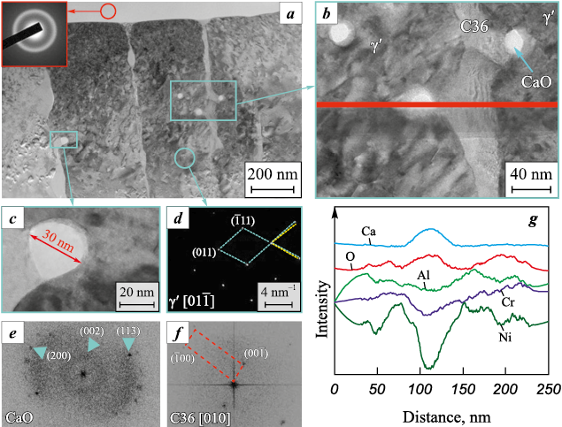
To investigate the structure of crack-free coatings obtained under anodic polarity in greater detail, the fine structure of the ACe sample was analyzed. A bright-field TEM image of a lamella cut from its surface is shown in Fig. 6, a (see also Fig. 3, c). The coating consists of columnar crystals with a strongly oriented growth direction along the [01–1] zone axis. An oxide particle located above the columnar crystals on the coating surface exhibits an amorphous structure, confirmed by electron diffraction showing an amorphous halo (inset in Fig. 6, a).
Fig. 6. Fine structure of the ACe sample obtained under anodic polarity in ESCAT |
The columnar crystals, ~300 nm in cross-section, consist of the γ′ phase with an ordered L12 crystal structure, as confirmed by electron diffraction. Analysis of the corresponding diffraction pattern (Fig. 6, d) revealed displacements of atomic planes, which may result from dislocation motion in the γ′ matrix.
Spherical nanoparticles up to 30 nm in size are mainly located along the boundaries of the columnar crystals (Fig. 6, c). Analysis of these particles (Figs. 6, b and g) showed that they are enriched in calcium and oxygen, while the concentrations of all other elements are significantly reduced. According to Fig. 6, d, these oxides have an orthorhombic lattice with a CaO-type structure.
In addition, the γ′ grain boundaries contain a highly distorted secondary phase (Fig. 6, b). EDS analysis determined its composition as Ni53.21Al20Cr15.85Co6.5Mo4.45 . The large interplanar spacing (d = 5.7 Å), obtained from the Fourier transform (Fig. 6, e), suggests that the diffraction originates from the [10–10] plane of a hexagonal Laves phase (AB2) of the C36 structure type. The calculated lattice parameters for this phase are а = 6.63 Å and с = 11.05 Å. Based on the elemental ratio, it can be assumed that the Laves phase has the composition (Ni,Co)2(Al,Cr,Mo).
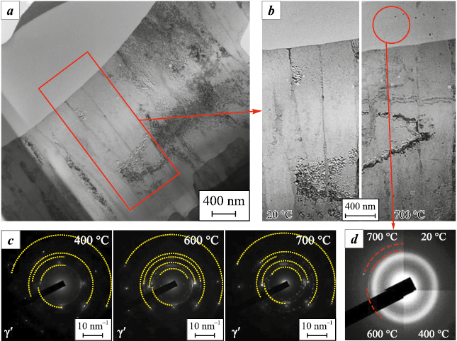
Fig. 7 shows the overall appearance of the lamella and enlarged images of the selected region before and after vacuum annealing at 700 °C. A distinct change in contrast in some areas indicates relaxation of internal stresses (Fig. 7, b). The series of electron diffraction patterns presented in Fig. 7, c, obtained from γ′ columnar crystals during lamella heating up to 700 °C, confirm the high thermal stability of this phase. At the same time, at 600 °C nanocrystalline particles appeared in the amorphous (AlCaCe)O particle located on the coating surface (Fig. 7, d). Their interplanar spacings (3.05 Å, 2.90 Å) correspond to a monoclinic CaAl2O4 mixed oxide.
Fig. 7. Overall view of the lamella (a), images before and after vacuum heating to 400 and 700 °C |
Mechanical and tribological properties of the coatings
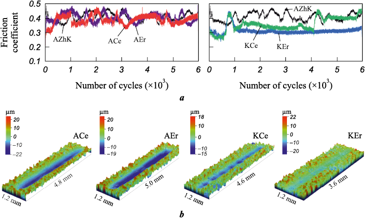
The results of instrumented nanoindentation (Fig. 8, a) showed that ESCAT increases the hardness and decreases the Young’s modulus (E) of the AZhK alloy substrate. The presence of Er in the coatings has a more pronounced effect on hardness compared with Ce alloying of the electrode. The maximum hardness values (12.3 ± 0.3 and 10.2 ± 0.3 GPa, respectively) were recorded when cathodic polarity was applied. Fig. 8, b also presents the H/E ratio, which is commonly used as an indicator of the damage tolerance of coatings. The coatings exhibit relatively low Young’s modulus values (E ≤ 160 GPa), which is atypical for intermetallics: 178 GPa for Ni3Al and 284 GPa for NiAl [14].
Fig. 8. Profiles of hardness (H) and Young’s modulus (E) across the sample thickness (a) |
As shown in Figs. 8, b and 9, b, ESCAT significantly improves the wear resistance of the nickel alloy, with the effect being stronger under cathodic polarity (up to a sixfold increase) compared with anodic polarity (up to a twofold increase). Erbium in the coating has a stronger influence on enhancing these properties. The effects of RE additions and electrode polarity on the wear resistance of the coatings correlate with the formation of a dual-intermetallic structure. In particular, coatings with a (β-NiAl + γ′-Ni3Al) structure, which exhibit the highest hardness, are characterized by excellent wear resistance, with values ranging from 6.0 to 7.5·10–5 mm3/(N·m).
Fig. 9. Friction coefficient curves (a) and 3D images of wear tracks (b) |
The friction coefficient versus cycle number curves shown in Fig. 9, a demonstrate the higher amplitude of friction fluctuations in contact with the steel ball for both the untreated AZhK alloy and after anodic ESCAT. The average friction coefficient values range from 0.45 to 0.35, while a further reduction to ~0.3 is observed for coatings produced under cathodic polarity (K-series).
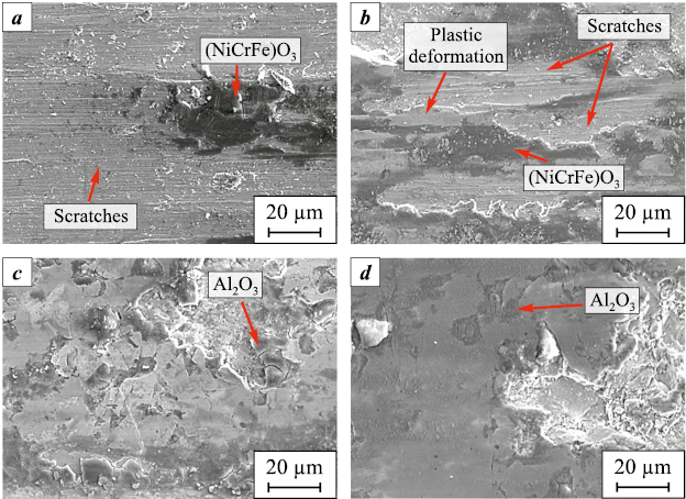
To investigate the wear mechanisms in greater detail, SEM images of the wear tracks were obtained (Fig. 10), and EDS analysis was performed. The results suggest two dominant wear mechanisms, which correlate with the coating structures determined by electrode polarity during ESCAT. In the case of A-series coatings, ball sliding is accompanied by the formation of deep grooves and numerous ridges, associated with local plastic deformation (Figs. 10, a and b).
Fig. 10. SEM secondary electron images of wear tracks for the samples: |
In contrast, the wear track surfaces of the K-series coatings display a different morphology, characterized by compacted wear debris formed under load during testing (Figs. 10, c and d). According to EDS data, the bottoms of the wear tracks are depleted in aluminum (28.2 at. % Al and 47.9 at. % Ni). At the same time, the wear debris consists mainly of Al2O3 , formed by selective oxidation of aluminum. Thus, wear of the K-series coatings is primarily governed by aluminum oxidation and compaction of the oxidized debris, processes which together promote the formation of a protective tribolayer.
High-temperature
oxidation resistance of the coatings
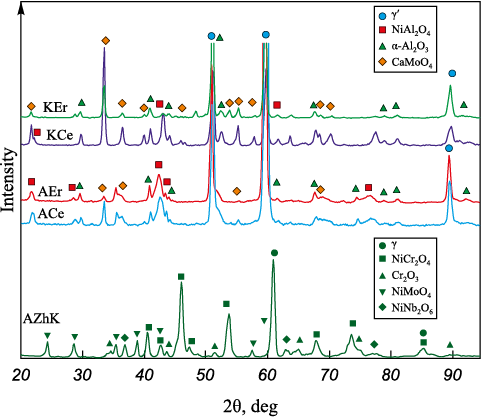
Fig. 11 and Table 4 show the results of qualitative and quantitative phase analysis of the samples after 30 h of oxidative annealing at 1000 °C. The XRD pattern of the AZhK alloy exhibits diffraction peaks corresponding to Cr2O3 and spinel phases NiCr2O4 , NiMoO4 , and NiNb2O6 .
Fig. 11. XRD patterns of the samples after 30 h
Table 4. Phase composition of the samples
| |||||||||||||||||||||||||||||||||||||||||||||||||||||||||||||||||||||||||||||||||||||||||||||||||||
Although the ESCAT coatings show a similar qualitative phase composition after long-term oxidative annealing, the quantitative phase ratios differ markedly (Table 4) and are dependent on electrode polarity. In the annealed coated samples, a large fraction of the γ′ phase is retained (30–72 wt. %). This suggests that the oxide layers formed on the coating surfaces are relatively thin and remain fully penetrable by X-rays under Bragg–Brentano geometry. Thus, after isothermal holding of the ACe and AEr coatings, the surface layer is dominated by α-Al2O3 and NiAl2O4 phases, while CaMoO4 is detected only in small amounts (up to 3 wt. %). In contrast, oxidation of the KCe and KEr coatings results in an increase in CaMoO4 content up to 15 wt. %, while the combined content of α-Al2O3 and NiAl2O4 reaches 25–56 wt. %.
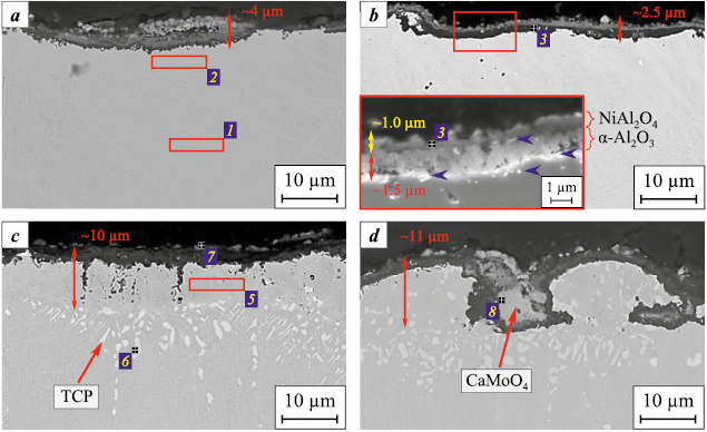
Cross-sectional images (Fig. 12) of the oxidized samples confirm the XRD results. The total thickness of the oxide layers formed on the coatings reaches 2.5 µm, which is up to 10 times thinner than the oxide layer on the AZhK alloy (~25 µm). The minimum oxide layer thickness was recorded for coatings produced under anodic polarity.
Fig. 12. SEM backscattered electron images of cross-sections |
The oxide layers exhibit a bilayer structure. The outer continuous NiAl2O4 layer has a spinel structure and contains finely dispersed CaMoO4 particles. Beneath it lies a layer of α-Al2O3 , whose boundaries (highlighted with blue arrows in the inset of Fig. 12, b) are enriched in Er and Ce. According to EDS (region 1, Table 5), the oxygen-free zone of the coating is depleted in Al (7.8 at. %). These results indicate that beneath the oxide layers there is a zone composed not of pure γ′ phase, as identified by XRD, but of γ′ + γ grains.
Table 5. EDS results of the regions shown in Fig. 12
| |||||||||||||||||||||||||||||||||||||||||||||||||||||||||||||||||||||||||||||||||||||||||||||||||||||||||||||
The oxide layers of the coatings produced under cathodic polarity (Figs. 12, c and d) also show a heterogeneous structure. CaMoO4 grains are found on the surface, beneath which lies a continuous NiAl2O4 + α-Al2O3 layer, also containing dispersed CaMoO4 particles. The oxygen-free zone of these coatings consists of γ′ grains, indicating a β → γ′ phase transformation driven by the interaction of aluminum with oxygen. Additionally, agglomerates of particles are present at the coating–substrate interface, a feature not observed in the A-series coatings. According to EDS (region 6, Table 5), these particles contain refractory elements consistent with topologically close-packed (TCP) phases.
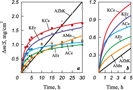
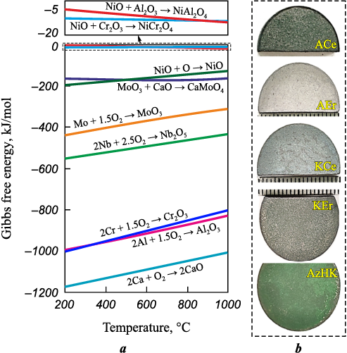
Fig. 13 shows the oxidation kinetics curves of the untreated and EST-treated samples during 30 h of isothermal exposure at 1000 °C. For comparison, the oxidation kinetics of a coating obtained under anodic polarity of ESCAT with an Al–7 at. % Ca–1 at. % Mn electrode (sample AMn) are also included. In Fig. 13, a, the experimental data are shown by solid lines, while the dashed lines represent approximations calculated by an empirical method using the equations given in Table 6. The relationship between mass gain and oxidation time for the AZhK alloy follows a linear law, as confirmed by approximation coefficients close to unity. For this sample (Fig. 14, b), after 30 h of isothermal exposure, a degraded green-colored surface is observed, which is most likely due to the formation of nickel or chromium oxides.
Fig. 13. Oxidation kinetics curves of the samples (a)
Table 6. Regression equation parameters
Fig. 14. Gibbs free energy of oxide formation (ΔG) as a function | |||||||||||||||||||||||||||||||||||
The oxidation kinetics curves confirm (Fig. 13) that the use of combined ESCAT with Al–Ca-based electrodes significantly improves the oxidation resistance of the AZhK superalloy at 1000 °C. While the mass gain of the AMn coating follows a parabolic law (Table 6), the oxidation of RE-containing coatings follows a logarithmic law. Overall, the oxidation curves of the coatings can be divided into two stages: an initial stage (0–5 h) and a steady stage (5–30 h). Despite the parabolic kinetics of the initial oxidation stage of the AMn sample, it shows the lowest slope of the curve (Fig. 13, b), indicating the slowest oxidation rate at this stage. In contrast, other samples with logarithmic oxidation show rapid mass gain during the initial stage, but in the steady stage the rate slows down as the oxide layer thickens. Thus, the transition from parabolic to logarithmic behavior is explained by the retardation of oxygen diffusion through the already formed oxide layer.
Discussion
The role of rare-earth metals in both coatings and nickel-based superalloys has been widely investigated [9; 16; 17]. However, a unified theory explaining the beneficial effects of such alloying has not yet been established. Alloying nickel-based superalloys with RE metals (Y, Ce, La, Hf, and Er), as well as applying RE-modified coatings, reduces oxidation rates by improving the crack resistance and adhesion of the oxide layer to the substrate. Small RE metals additions accelerate the nucleation of chromium and aluminum oxides [18], thereby promoting rapid formation of a protective layer. Owing to their large atomic radii and high chemical activity, RE form dispersed phases in coatings (e.g., NixAly(Hf,Zr)z [19], LaCrO3 [20]) that hinder grain boundary diffusion of cations (Al3+, Cr3+, Ni2+, Ta5+ [21; 22]). For instance, [23] reported that the presence of Ce (0.038 wt. %) increases aluminum activity in the IC21 superalloy with an Al–Si coating after oxidative annealing at 1150 °C, reducing the Al content required for the formation of a protective α-Al2O3 layer. Ce also retards the polymorphic transformation of metastable θ-Al2O3 into stable α-Al2O3 , thereby suppressing volumetric shrinkage of the oxide layer [24] and lowering the likelihood of crack formation.
Excessive RE additions, however, coarsen the microstructure and degrade the mechanical properties of alloys [25], and may also lead to degradation of the oxide scale. Therefore, electrode compositions were selected to be close to the eutectic point on the phase diagram, allowing the formation of a fluid reactive melt on the metal surface during ESCAT that actively interacts with substrate elements. Although the RE content in the coatings does not exceed 0.5 at. %, this level is sufficient to significantly influence their properties.
The polarity of the electrodes during ESCAT governs the structural and phase transformations in the coatings. Since this processing is carried out in vacuum [10; 12], spark breakdown during electrode retraction is accompanied not only by energy release at the anode, but also by pulsed arc evaporation of the cathode (Fig. 15). Under cathodic polarity, additional electrode sputtering increases the substrate mass gain and coating thickness, whereas anodic polarity leads to partial evaporation of the coating surface.
Fig. 15. Schematic illustration of the ESCAT process |
β-NiAl-based coatings can only be obtained under cathodic polarity, because intensive electrode evaporation enriches the coating with aluminum. Such coatings, however, are prone to cracking due to the mismatch between the thermal expansion coefficients of β-NiAl (15·10−6 K–1 [26]) and Ni-based superalloys (12·10−6 K−1 [27]). They also exhibit a weaker crystallographic texture (Figs. 6, c and d), resulting from stronger substrate heating.
Anodic polarity promotes the formation of γ′-Ni3(AlCr)-based coatings. Minimal substrate heating under these conditions enables efficient heat dissipation into the bulk [28; 29], supporting uniform grain growth with a dominant <100> crystallographic orientation. The reduced cross-section of the columnar crystallites compared with the AZhK alloy (inset in Fig. 5, a) is associated with the ultrahigh solidification rates typical of ESCAT [30; 31], which overall enhances hardness and wear resistance. In addition, in-situ formation of (Al–Ca–RE)O nanoparticles along grain boundaries restricts dislocation motion by generating dislocation loops. The strengthening role of oxide inclusions has also been noted in [32].
Regardless of electrode polarity, oxidation of the coatings follows a logarithmic law: a rapid mass gain during the initial stage is followed by a slower increase as the oxide layer thickens. The high oxidation rate at the early stage is associated with selective oxidation of Al, accompanied by Al2O3 formation (–890.4 kJ/mol) (Fig. 14, a). The presence of (Al–Ca–RE)O nanoparticles appears to accelerate Al2O3 formation. The solubility of RE in Al2O3 or Cr2O3 is very low [19], so their oxides segregate at the metal–oxide interface (Fig. 13, b). Furthermore, as shown in Fig. 7, vacuum annealing of the coatings results in the crystallization of CaAl2O4 nanoparticles, which are isostructural with alumina. Owing to their lower energy, these particles accelerate Al2O3 grain growth. At the boundaries of the thin α-Al2O3 layer, RE-enriched particles improve oxide adhesion and reduce stress concentrations, thereby preventing crack formation.
Prolonged isothermal exposure of ACe and AEr coatings in oxygen-containing environments leads to the formation of NiAl2O4 (–12.5 kJ/mol) through Ni diffusion across the thin Al2O3 film to the surface. Thus, in these coatings oxygen diffusion is strongly restricted by the heterogeneous NiAl2O4/α-Al2O3 layer, reinforced by CaMoO4 particles. This interpretation is consistent with the low oxidation rate constants (Kp = 0.16–0.22) compared with those of the KCe and KEr coatings (Table 6).
Despite the presence of cracks, the KCe and KEr coatings exhibit lower mass gain than the AZhK alloy. Oxygen diffusion along cracks occurs during the first ~15 h of oxidation, after which the growth of CaMoO4 grains within the cracks blocks further diffusion. The cracks thus act as channels for upward Mo diffusion, necessary for CaMoO4 grain nucleation and subsequent coalescence into a continuous layer. According to [8], these grains with the tetragonal scheelite structure I41/a exhibit excellent thermal stability and ultralow thermal conductivity at 400–1000 K (0.6–1.2 W/(m·K)), values even lower than those of thermal barrier coatings such as YSZ (1.5–3.0 W/(m·K)).
Conclusion
The formation behavior of wear- and oxidation-resistant coatings produced by combined electrospark and cathodic arc treatment (ESCAT) on AZhK nickel-based superalloy samples was investigated. Optimal ESCAT modes with Al–Ca–Er and Al–Ca–Ce electrodes were identified, enabling the formation of 15–20 µm thick coatings composed of columnar crystallites with a cross-section below 300 nm, containing γ′-Ni3Al and β-NiAl phases. These coatings increased substrate hardness from 5.2 to 12.3 GPa and improved wear resistance sixfold. The use of Al–Ca–Er electrodes provided enhanced oxidation resistance of the AZhK alloy at 1000 °C by changing the oxidation law from linear to logarithmic one due to the formation of a protective NiAl2O4 /α-Al2O3 layer ~3 µm thick, reinforced by CaMoO4 particles.
References
1. Kablov E.N. Strategical areas of developing materials and their processing technologies for the period up to 2030. Aviatsionnye materialy i tekhnologii. 2012;(S):7–17. (In Russ.).
2. Long H., Mao S., Liu Y., Zhang Z., Han X. Microstructural and compositional design of Ni-based single crystalline superalloys. A review. Journal of Alloys and Compounds. 2018;743:203–220. https://doi.org/10.1016/j.jallcom.2018.01.224
3. Sirotin N.N., Marchukov E.Yu., Novikov A.S. Damageability and operability of aviation gas turbine engines: Handbook. Moscow: Nauka; 2015. 551 p. (In Russ.).
4. Xie Yu., Wang M.. Epitaxial MCrAlY coating on a Ni-base superalloy produced by electrospark deposition. Surface and Coatings Technology. 2006; 201(6):3564–3570. https://doi.org/10.1016/j.surfcoat.2006.08.107
5. Zamulaeva E.I., Levashov E.A., Sviridova T.A., Shvyndina N.V., Petrzhik M.I. Pulsed electrospark deposition of MAX phase Cr2AlC based coatings on titanium alloy. Surface and Coatings Technology. 2013;235:454–460. https://doi.org/10.1016/j.surfcoat.2013.08.002
6. Burkov A.A., Chigrin P.G., Kulik M.A. Effect of TaC content on microstructure and wear behavior of PRMMC Fe-TaC coating manufactured by electrospark deposition on AISI304 stainless steel. Surface and Coatings Technology. 2024;494(2):131446. https://doi.org/10.1016/j.surfcoat.2024.131446
7. Mukanov S.K., Petrzhik M.I., Loginov P.A., Levashov E.A. Influence of manganese alloying on the structure and properties of electrospark coatings of EP741NP heat-resistant nickel LPBF alloy. Izvestiya. Non-Ferrous Metallurgy. 2024;(2):70–84. https://doi.org/10.17073/0021-3438-2024-2-70-84
8. Mukanov S.K., Petrzhik M.I., Kudryashov A.E., Naumova E.A., Baskov F.A., Loginov P.A., Levashov E.A. Enhancing high-temperature oxidation resistance of nickel superalloy obtained by laser powder bed fusion via reactive electric spark treatment. Transactions of Nonferrous Metals Society of China. 2024;34(12):3935–3948. https://doi.org/10.1016/S1003-6326(24)66649-5
9. Li J.G., Wang N., Liu J.D., Xu W. Influence of rare earth elements (Y, La and Ce) on the mechanical properties and oxidation resistance of nickel-based superalloys: A critical review. Journal of Materials Science & Technology. 2024;195:9–21. https://doi.org/10.1016/j.jmst.2023.11.077
10. Kuptsov K.A., Sheveyko A.N., Sidorenko D.A., Shtansky D.V. Electro-spark deposition in vacuum using graphite electrode at different electrode polarities: Peculiarities of microstructure, electrochemical and tribological properties. Applied Surface Science. 2021;566:150722. https://doi.org/10.1016/j.apsusc.2021.150722
11. Baskov F.A., Sentyurina Zh.A., Logachev I.A., Krutikov N.I., Levashov E.A. Influence of HIP and heat treatment on the structure and properties of AJKh nickel heat-resistant alloy obtained by SLM. In: Proceedings of the 12th International Symposium “Powder Metallurgy: Surface Engineering, New Powder Composite Materials, Welding” (Minsk, April 7–9, 2021). Minsk: Belaruskaya navuka; 2021. Part 1. P. 136–141. (In Russ.).
12. Naumova E.A., Vasina M.A., Chernogorova O.P., Rogachev S.O., Zadorozhnyi M.Yu., Bobrysheva A.O. Investigation of the effect of cerium on the structure and properties of calcium-containing aluminum alloys. Metallurgist. 2024;67:1302–1314. https://doi.org/10.1007/s11015-024-01622-8
13. Sheveyko A.N., Kuptsov K.A., Kiryukhantsev-Korneev Ph.V., Kaplansky Yu.Yu., Orekhov A.S., Levashov E.A. Protective coatings for LPBF Ni-based superalloys using a combination of electrospark deposition and pulsed arc evaporation methods. Applied Surface Science. 2022;581:152357. https://doi.org/10.1016/j.apsusc.2021.152357
14. Buntushkin V.P., Bazyleva O.A., Burkina V.I. High-temperature heat-resistant alloys based on the Ni3Al intermetallic compound for hot section parts of gas turbine engines. Aviatsionnaya promyshlennost’. 2007;(2):41–43. (In Russ.).
15. Bale C.W., Bélisle E., Chartrand P., Decterov S.A., Eriksson G., Gheribi A.E., Hack K., Jung I.H., Kang Y.B., Melançon J., Pelton A.D., Petersen S., Robelin C., Sangster J., Spencer P., Van Ende M.A. Reprint of: FactSage thermochemical software and databases. Calphad. 2016; 55(1):1–19. https://doi.org/10.1016/j.calphad.2016.07.004
16. Thanneeru R., Patil S., Deshpande S., Seal S. Effect of trivalent rare earth dopants in nanocrystalline ceria coatings for high-temperature oxidation resistance. Acta Materialia. 2007;55(10):3457–3466. https://doi.org/10.1016/j.actamat.2007.01.043
17. Pint B.A. Experimental observations in support of the dynamic-segregation theory to explain the reactive-element effect. Oxidation of Metals. 1996;45(1):1–37. https://doi.org/10.1007/BF01046818
18. Dai J., Zhu J., Chen C., Weng F. High temperature oxidation behavior and research status of modifications on improving high temperature oxidation resistance of titanium alloys and titanium aluminides: A review. Journal of Alloys and Compounds. 2016;685:784–798. https://doi.org/10.1016/j.jallcom.2016.06.212
19. Chevalier S. What did we learn on the reactive element effect in chromia scale since Pfeil’s patent? Materials and Corrosion. 2014;65(2):109–115. https://doi.org/10.1002/maco.201307310
20. Guo H., Li D., Zheng L., Gong S., Xu H. Effect of co-doping of two reactive elements on alumina scale growth of β-NiAl at 1200 °C. Corrosion Science. 2014;88:197–208. https://doi.org/10.1016/j.corsci.2014.07.036
21. Song X., Wang L., Liu Y., Ma H. Effects of temperature and rare earth content on oxidation resistance of Ni-based superalloy. Progress in natural science: Materials International. 2011;21(3):227–235. https://doi.org/10.1016/S1002-0071(12)60035-5
22. Daroonparvar M., Yajid M.A.M., Kay C.M., Bakhsheshi-Rad H., Gupta R.K., Yusof N.M., Ghandvar H., Arshad A., Zulkifli I.S.M. Effects of Al2O3 diffusion barrier layer (including Y-containing small oxide precipitates) and nanostructured YSZ top coat on the oxidation behavior of HVOF NiCoCrAlTaY/APS YSZ coatings at 1100 °C. Corrosion Science. 2018;144:13–34. https://doi.org/10.1016/j.corsci.2018.07.013
23. Pang X.J., Li S.S., Qin L., Pei Y.L., Gong Sh.K. Effect of trace Ce on high-temperature oxidation behavior of an Al–Si-coated Ni-based single crystal superalloy. Journal of Iron and Steel Research International. 2019;26(1):78–83. https://doi.org/10.1007/s42243-018-0214-0
24. Pint B.A., Treska M., Hobbs L.W. The effect of various oxide dispersions on the phase composition and morphology of Al2O3 scales grown on β-NiAl. Oxidation of Metals. 1997;47(1):1–20. https://doi.org/10.1007/BF01682369
25. Wang H., Wang A., Li C., Yu X., Xie J., Liang T., Liu C. Effects of rare earth metals on microstructure, mechanical properties, and pitting corrosion of 27 % Cr hyper duplex stainless steel. Reviews on Advanced Materials Science. 2022;61(1):873–887. https://doi.org/10.1515/rams-2022-0284
26. Yuan J., Wang Q., Liu X., Lou S., Li Q., Wang Z. Microstructures and high-temperature wear behavior of NiAl/WC-Fex coatings on carbon steel by plasma cladding. Journal of Alloys and Compounds. 2020;842:155850. https://doi.org/10.1016/j.jallcom.2020.155850
27. Sung P.K., Poirier D.R. Estimation of densities and coefficients of thermal expansion of solid Ni-base superalloys. Materials Science and Engineering: A. 1998;245:135–141. https://doi.org/10.1016/S0921-5093(97)00699-0
28. Xie Y.J., Wang M.C. Epitaxial MCrAlY coating on a Ni-base superalloy produced by electrospark deposition. Surface and Coatings Technology. 2006;201(6):3564–3570. https://doi.org/10.1016/j.surfcoat.2006.08.107
29. Xie Y.J., Wang M.C. Microstructural morphology of electrospark deposition layer of a high gamma prime superalloy. Surface and Coatings Technology. 2006; 201(3–4):691–698. https://doi.org/10.1016/j.surfcoat.2005.12.034
30. Petrzhik M., Molokanov V., Levashov E. On conditions of bulk and surface glass formation of metallic alloys. Journal of Alloys and Compounds. 2017;707:68–72. https://doi.org/10.1016/j.jallcom.2016.12.293
31. Mukanov S.K., Petrzhik M.I., Kudryashov A.E., Baskov F.A., Levashov E.A. Improving the wear and heat resistance of niobium substrate via reactive electrospark treatment using fusible AlCaSiY electrode. Applied Surface Science. 2024;670:160663. https://doi.org/10.1016/j.apsusc.2024.160663
32. Liu Y., Yang L., Yang X., Zhang T., Sun R. Optimization of microstructure and properties of composite coatings by laser cladding on titanium alloy. Ceramics International. 2021;47(2):2230–2243. https://doi.org/10.1016/j.ceramint.2020.09.063
About the Authors
S. K. MukanovRussian Federation
Samat K. Mukanov – Cand. Sci. (Eng.), Research Scientist of the Scientific Educational Center of Self–Propagating High-Temperature Synthesis (SHS-Center) of MISIS–ISMAN
1 Bld, 4 Leninskiy Prosp., Moscow 119049, Russia
M. I. Petrzhik
Russian Federation
Mikhail I. Petrzhik – Dr. Sci. (Eng.), Professor of Department at Powder Metallurgy and Functional Coatings (PM&FC), NUST MISIS; Leading Research Scientist of the SHS-Center, MISIS–ISMAN
1 Bld, 4 Leninskiy Prosp., Moscow 119049, Russia
A. E. Kudryashov
Russian Federation
Alexander E. Kudryashov – Cand. Sci. (Eng.), Leading Research Scientist of the SHS-Center, MISIS–ISMAN
1 Bld, 4 Leninskiy Prosp., Moscow 119049, Russia
P. A. Loginov
Russian Federation
Pavel A. Loginov – Dr. Sci. (Eng.), Senior Lecturer of the Department of PM&FC, NUST MISIS; Senior Research Scientist of SHS-Center, MISIS–ISMAN
1 Bld, 4 Leninskiy Prosp., Moscow 119049, Russia
N. V. Shvyndina
Russian Federation
Nataliya V. Shvyndina – Leading Engineer of SHS-Center, MISIS–ISMAN
1 Bld, 4 Leninskiy Prosp., Moscow 119049, Russia
A. N. Sheveyko
Russian Federation
Aleksandr N. Sheveyko – Research Scientist of the SHS-Center, MISIS–ISMAN
1 Bld, 4 Leninskiy Prosp., Moscow 119049, Russia
K. A. Kuptsov
Russian Federation
Konstantin A. Kuptsov – Cand. Sci. (Eng.), Senior Research Scientist of the SHS-Center, MISIS–ISMAN
1 Bld, 4 Leninskiy Prosp., Moscow 119049, Russia
E. A. Levashov
Russian Federation
Evgeny A. Levashov – Dr. Sci. (Eng.), Professor, Corresponding Member of the RAS, Head of the Department PM&FС, NUST MISIS; Head of SHS-Center, MISIS–ISMAN
1 Bld, 4 Leninskiy Prosp., Moscow 119049, Russia
Review
For citations:
Mukanov S.K., Petrzhik M.I., Kudryashov A.E., Loginov P.A., Shvyndina N.V., Sheveyko A.N., Kuptsov K.A., Levashov E.A. Combined technology of electrospark and cathodic-arc formation of wear- and oxidation resistant coatings. Powder Metallurgy аnd Functional Coatings (Izvestiya Vuzov. Poroshkovaya Metallurgiya i Funktsional'nye Pokrytiya). 2025;19(4):60-76. https://doi.org/10.17073/1997-308X-2025-4-60-76
JATS XML


