Scroll to:
Titanium carbide coating for high-temperature graphite components
https://doi.org/10.17073/1997-308X-2025-5-70-79
Abstract
Titanium carbide (TiC) coatings were produced on the surface of graphite components using a low-cost liquid-phase technique involving application of a TiO2-based reaction mixture followed by carbothermal annealing in vacuum at 1900 °C. Typical grades of structural graphite (GMZ, MPG-6, and I-3) commonly used in high-temperature graphite assemblies were employed as substrates for the protective coating. The resulting polycrystalline titanium carbide films (NaCl-type structure) exhibited an axial growth texture [111] and thermal stresses that depended on the graphite grade, caused by the difference in the coefficients of thermal expansion between titanium carbide and graphite. Typical coating thicknesses ranged from 10 to 20 µm. Graphite components with TiC coatings were successfully tested under high-temperature silicon carbide single-crystal growth conditions. The tribological properties of the coatings were also evaluated. The use of denser grades of isostatic graphite (I-3) is preferable due to the formation of a dense two-dimensional structure of the protective layer on the graphite surface.
For citations:
Afanas’ev А.V., Bykov Yu.О., Lebedev А.О., Markov А.V., Sharenkova N.V., Latnikova N.M. Titanium carbide coating for high-temperature graphite components. Powder Metallurgy аnd Functional Coatings (Izvestiya Vuzov. Poroshkovaya Metallurgiya i Funktsional'nye Pokrytiya). 2025;19(5):70-79. https://doi.org/10.17073/1997-308X-2025-5-70-79
Introduction
Single-crystal silicon carbide is currently in demand for manufacturing components of power, high-frequency, and high-temperature electronic devices [1]. Single-crystal SiC ingots are typically grown by the sublimation method (modified Lely process), developed by Tairov and Tsvetkov at LETI Institute, on their own seeds, in vacuum or in an inert atmosphere (usually argon) at a temperature of about 2000 °C, using high-purity silicon carbide powder as the source material. The graphite components used in the standard process of the modified Lely method are exposed to an aggressive vapor–gas environment containing volatile species Si, SiC2 , and Si2C, which causes corrosion and leads to contamination of the crystal ingot with graphite particles [2].
To protect the surface of graphite assemblies, tantalum carbide films are typically used [3]. They remain stable at t > 2000 °C and can be produced by various methods. However, tantalum carbide coatings are relatively expensive, particularly when applied to components intended for single use. Therefore, it is necessary to search for more cost-effective coating materials that can serve as efficient protective barriers to prevent corrosion of graphite assemblies. Their surface can also be protected using other high-temperature carbides such as TiC, WC, VC, and others [4; 5]. Among them, titanium carbide is of greatest interest, as it provides an optimal balance of high hardness (up to 2400 HV and higher), corrosion resistance, and thermal stability.
The properties of TiC depend on the synthesis method [6]. Chemical vapor deposition (CVD) methods [7–9] are widely used industrially for corrosion-resistant materials; the resulting coatings exhibit high adhesion and uniformity on flat surfaces. However, these methods are costly (due to equipment and large consumption of carrier gases) and characterized by low growth rates (typically producing coatings about 2–3 µm thick), as well as by the use of toxic or pyrophoric precursors [9]. The use of plasma enables coating of substrates and surfaces sensitive to high temperatures; such coatings are distinguished by high adhesion and low surface roughness [10].
The family of physical vapor deposition (PVD) methods includes thermal evaporation, ion sputtering, cathodic arc deposition, and electron-beam evaporation [11–13]; the most common heating method among them is indirect resistive heating. The coatings produced by these methods exhibit high hardness and wear resistance but insufficient adhesion to the substrate. Moreover, nonuniform coating thickness is observed inside cavities or on components with complex geometry.
The use of magnetron sputtering systems, including reactive and radio-frequency sputtering [14–17], enhances process efficiency by enabling deposition of uniform films over large areas. Additional annealing of coatings [14] improves the crystallinity of TiC films and increases the grain size. The actual coating thickness achieved and applied in practice remains small (a few micrometers), yet such films have a dense structure without cavities or cracks. The challenge of coating sidewalls and complex profiles is addressed using advanced magnetron control mechanisms.
Laser cladding of titanium carbide–reinforced composite coatings is effectively employed for surface passivation or surface hardening [18], but it cannot be used for large-area deposition. Pulsed laser deposition (PLD) involves the use of a laser to ablate material from a target [19]. The disadvantages of this method include its limited suitability for mass production, the dependence of ablation on laser energy, and nonuniform coating formation on complex surfaces.
Titanium carbide coatings can also be produced by several other methods. In [20], a TiC-containing coating was produced by plasma transferred arc welding (PTAW), which increased the corrosion potential of the substrate and significantly reduced the corrosion current density. Methods based on in-situ carburizing of titanium in a CaCl2–CaC2 molten salt – the salt-thermo-carburizing route [21] – or on anodic polarization–accelerated TiC coating formation in molten salt [22] are also applicable. These approaches are simple and provide high coating growth rates (over 100 µm in 8 h [21] and about 15 µm in 0.7 h [22]).
Overall, none of the methods reviewed combines all the required characteristics for producing low-cost functional corrosion-resistant TiC-based coatings for graphite components used in high-temperature processes of silicon carbide and aluminum nitride synthesis. Therefore, there is a need to identify the most economical coating techniques that do not require expensive equipment and can yield dense protective layers tens of micrometers thick.
Experimental procedure
In this study, a titanium carbide (TiC) film coating was produced by applying a reaction mixture containing powdered titanium dioxide TiO2 (OSCh 7–3), an adhesive, and a solvent onto graphite components. Various phenol–formaldehyde resins were used as adhesives, and ethyl alcohol served as the solvent. The mixture was applied at room temperature to the surface of graphite components made of different graphite grades. The coated components were dried in air at t = 80÷100 °C, followed by annealing of the applied coating in forevacuum at temperatures up to 1900 °C for 4–5 h.
Graphite parts of commonly used domestic grades were employed as substrates for titanium carbide coating deposition, namely low-ash extruded graphite GMZ [23], fine-grained dense pressed graphite MPG-6 [24], and isostatic graphite I-3 [25].
The resulting coatings were examined by X-ray diffraction (XRD) for structural and phase composition analysis, scanning electron microscopy (SEM), optical microscopy (OM), energy-dispersive spectroscopy (SEM–EDS), profilometry, and tribometry.
The phase composition of the products at different stages of synthesis was studied using a D2 Phaser X-ray diffractometer (Bruker AXS, Germany) equipped with a copper anode X-ray tube and a nickel β-filter. The phase identification was carried out using the EVA software package (Bruker AXS, Germany) with the ICDD PDF-2 diffraction database, release 2014 (PDF-2 Powder Diffraction File-2, ICDD, 2014). To calculate the unit cell parameters of TiC, sodium chloride (NaCl) was used as an internal standard, certified with the XRD powder standard Si640f (NIST, Gaithersburg, Maryland, USA). The calculations were performed using the Rietveld refinement method implemented in Topas-5 (Bruker). The error did not exceed ±0.0001 Å.
XRD analysis was used to determine the lattice parameters, texture, crystallite size, and second-order microstrain.
Second-order stresses (microstresses within crystallite or mosaic block volumes) and the size of the coherent scattering regions (CSR) were estimated from the broadening of X-ray reflections obtained from θ/2θ scans on the diffractometer. The observed line broadening generally includes the following contributions: instrumental broadening, size broadening due to small crystallite size (i.e., CSR dimension), and strain broadening caused by lattice microdeformation [26]. The size–strain separation was performed using the Williamson–Hall method [26], which considers the dependence of reflection broadening on the reflection order (for the first and third orders – 111 and 333 – of the cubic titanium carbide lattice). The instrumental contribution was determined from peak widths of nearly perfect single crystals (Si and Ge) measured at similar diffraction angles.
For Bragg angles corresponding to the 111 and 333 reflections of TiC, high-quality single-crystal silicon and germanium standards were used to evaluate the instrumental broadening. For the 111 reflection at 2θ ≈ 35.9°, the instrumental component was
βinstr = 1.9∙10–4 rad,
and for the 333 reflection (2θ ≈ 135.1°) it was
βinstr = 7.0∙10–4 rad.
The diffraction profiles followed a Gaussian distribution; therefore, the total line broadening was calculated by summing the squared components from different sources as follows:
\[\beta _\sum ^2 = \beta _{{\rm{instr}}}^2 + \beta _{{\varepsilon _n}}^2 + \beta _{{L_n}}^2 = \beta _{{\rm{instr}}}^2 + \beta _{{\rm{phys}}}^2,\]
where βΣ is the total broadening; βinstr is instrumental broadening; \({\beta _{{\varepsilon _n}}}\) is the broadening caused by lattice strain along the diffraction vector; \({\beta _{{L_n}}}\) is the size broadening due to the finite CSR dimension; βphys is the physical broadening. It is known that
| \[{\beta _{{\varepsilon _n}}} = 4{\varepsilon _n}{\rm{tg}}\theta ,\] | (1) |
| \[{\beta _{{L_n}}} = \frac{\lambda }{{{L_n}\cos \theta }},\] | (2) |
where εn = Δd/d, d is the interplanar spacing.
The coating thicknesses were determined by SEM, SEM–EDS, and OM from polished cross-sections of the “titanium carbide – graphite substrate” structures. Cross-sections were prepared from the end faces of the structures by breaking or cutting samples, followed by facing, grinding, and polishing operations.
The tribological properties of the TiC coating (10 μm thick) on a graphite substrate (grade I-3) were evaluated using counterbodies made of structural steel (ShKh-15) and zirconia (ZrO2 ) on an FMT-5000 tribometer according to the standard disk–ball test configuration. The disk rotation speed was 60 rpm (linear speed 0.03 cm/s), the wear track radius was 5 mm, and the applied load range was 10–200 N.
To assess the chemical stability, graphite components with TiC protective coatings were held at 2100 °C for 10 h in the presence of SiC powder.
Results and discussion
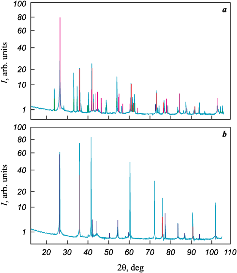
Synthesis mechanism. According to estimates reported in [27], the chemical reaction between titanium oxide and carbon powders starts at t = 1300 °С, and a single-phase titanium carbide is formed at about 1500 °C It was also noted in [28] that the degree of conversion of titanium dioxide to titanium carbide approaches unity in the temperature range of 1500–3340 K. XRD phase identification of the product obtained by holding the TiO2-based reaction mixture applied to graphite components at 1500 °C for 1 h in forevacuum (<1 Pa) (Fig. 1, a) revealed a mixture of the oxides Ti2O3 and TiO together with the titanium carbides TiC0.957 and TiC.
Fig. 1. X-ray diffraction patterns (CuKα radiation) |
Thus, it can be assumed that the transformation proceeds through intermediate stages involving the formation of lower oxides (TiO and Ti2O3 ), in accordance with the principle proposed by A.A. Baykov [29]:
TiO2 → Ti2O3 → TiO → TiC.
After holding at t = 1900 °С for 1 h under forevacuum conditions (Fig. 1, b), the reaction of carbide formation was complete for all graphite grades. The main phase was cubic TiC0.957 (hamrabayevite, NaCl-type structure) with a small amount of graphite, which apparently resulted from carbonization of the adhesive.
As noted in [30], the high rate of solid-state carbothermal reactions of oxide carburization can be explained by the formation of a vapor phase that adsorbs onto carbon surfaces. In this study, in addition to vapor-phase transport, we observed redistribution of the reaction mixture along the graphite surface via flows of a liquid phase (likely TiO2 ).
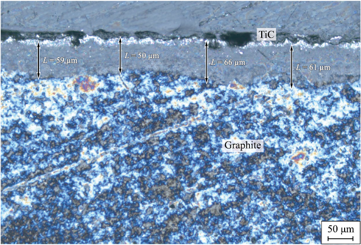
Coating thickness. In fracture cross-sections of the TiC-on-graphite structure, the coating thickness could not be determined by optical microscopy (OM) because of insufficient contrast. After polishing, a strong optical contrast appeared due to the substantial difference in mechanical properties between titanium carbide and graphite, enabling thickness estimation (Fig. 2). Since graphite is highly porous and the transformation of oxides into carbide occurs via participation of a liquid phase, OM observations of polished sections may overestimate the coating thickness.
Fig. 2. Optical micrograph of a polished cross section |
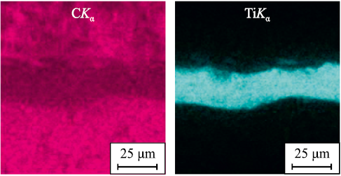
SEM–EDS mapping of the same structure (Fig. 3) yielded significantly smaller thickness values – 20–25 μm compared to 50–60 μm in Fig. 2.
Fig. 3. SEM image of a polished cross section |
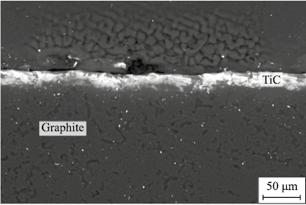
Penetration of the liquid oxide into graphite pores and its reaction with the substrate lead to blurring of the TiC–graphite interface and to the formation of an extended composite interlayer beneath the TiC coating, composed predominantly of graphite. This interfacial blurring is evident in Fig. 4.
Fig. 4. SEM image of a polished cross section |
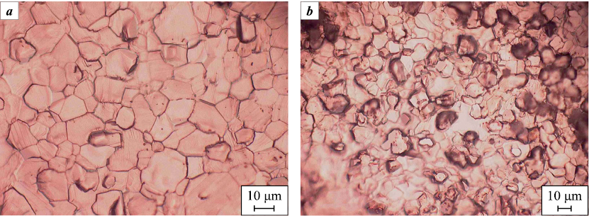
Morphology. On isostatic graphite, the titanium carbide coating generally exhibited a dense, flat surface composed of fused crystallites with sizes of 10–30 μm (Fig. 5, a). For less dense graphite grades, the surface appeared more developed, consisting of columnar crystallites poorly bonded to each other (Fig. 5, b).
Fig. 5. Surface morphology of the protective coating (optical microscopy image) |
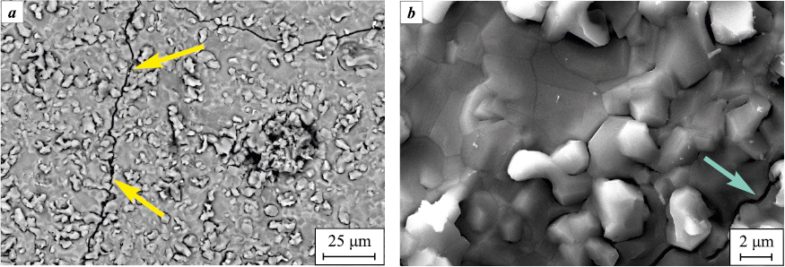
Structural defects. In thicker coatings (>30 μm), local cracking was observed, evidently caused by the difference in the linear coefficients of thermal expansion (CTE) between the coating and the substrate for all graphite grades (Fig. 6). First-order (macroscopic) stresses were confirmed by XRD (see Table 2).
Fig. 6. SEM image of the coating surface on GMZ graphite at different magnification |
Texture analysis. Protective coatings obtained on graphite components by chemical vapor deposition (CVD) methods usually exhibit a pronounced axial growth texture oriented normal to the graphite surface (for example, this is noted for tantalum carbide coatings in [31]).
For protective applications, the most favorable state is texture-free, as it is associated with the absence of through cracks [31]. However, a weak growth texture contributes to improved crystallite bonding and enhances the smoothness and continuity of the coating layer.
To evaluate the growth texture, XRD (θ–2θ) reflection intensities were measured after background subtraction for TiC films deposited on graphite plates made from the selected grades (sample 1 – GMZ, 2 – MPG-6, 3 – I-3). A polycrystalline TiC reference from the ASTM card No. 35-0801 [32] and a TiC powder synthesized in-house (without a graphite substrate) were used for comparison. The reflection intensities normalized to the intensity of the (111) reflection of the corresponding sample are presented in Table 1.
Table 1. Intensities of X-ray diffraction peaks
| |||||||||||||||||||||||||||||||||||||||||||||||||||||
According to Table 1, samples 1–3 are, with high confidence, characterized by a pronounced axial [111] growth texture.
Determination of the lattice period and first-order stresses. The measured lattice parameters of TiC are presented in Table 2 (the measurement uncertainty was ±0.0001 Å). According to the ASTM database, the equilibrium lattice parameter of titanium carbide is аeq = 4.3274(2) Å. The values of TiC lattice strain on graphite substrates of different grades, listed in Table 2, are of the same sign in all cases, which suggests the presence of thermal stresses at the TiC–graphite interface. As is well known, graphite grades exhibit high anisotropy and a wide range of linear coefficients of thermal expansion (CTE); however, literature data on CTE values for specific graphite grades are scarce [33–36]. An exception is represented by isostatic graphites, which are characterized by isotropic physical properties. The CTE values of the graphite grades used are also given in Table 2. For comparison, the CTE of titanium carbide is (7.0÷8.0)∙10–6 K–1 [29; 37].
Table 2. Lattice parameter a of TiC and related characteristics
|
As can be seen from Table 2, the strain values are not only of the same sign (positive) but also correlate with the differences between the CTE of TiC and that of the corresponding graphite substrate. Note also that isostatic graphite is not the best substrate for a TiC film owing to the high stress level generated in the coating.
Measurement of crystallite size and inhomogeneous lattice microstrain. The calculated results are summarized in Table 3.
Table 3. Analysis of X-ray peaks broadening factors
|
It is well known that, according to Eqs. (1) and (2), the ratio β333/β111 lies within the bounds
\[\left( {\frac{{\cos {\theta _{111}}}}{{\cos {\theta _{333}}}} = 2.49} \right) < \frac{{{\beta _{333}}}}{{{\beta _{111}}}} < \left( {\frac{{{\rm{tg}}{\theta _{333}}}}{{{\rm{tg}}{\theta _{111}}}} = 7.48} \right).\]
When β333/β111 approaches the cosine ratio, the line broadening is governed primarily by the finite crystallite size (i.e., the limited coherent scattering region, CSR). Conversely, when the ratio approaches the tangent ratio, microstrain provides the dominant contribution to broadening. As seen from Table 3, for all graphite substrates the principal contribution arises from the limited CSR (crystallite) size, which – within the measurement uncertainty – is on the order of 103 Å.
Tribological testing. During wear testing of the TiC coating (Vickers hardness 3000 HV, thickness 10 µm) deposited on a graphite substrate (500 HV) in disk configuration and tested against a ShKh15 steel ball (1900 HV), no coating wear was observed. When the TiC coating was tested against zirconium dioxide (ZrO2 , 12,000 HV), coating wear occurred, and it was four times greater than the wear of the ZrO2 ceramic ball. In this case, the TiC coating began to fail at loads ≥90 N, accompanied by a sharp increase and scatter (instability) in the friction force and an exponential increase in the penetration rate of the ZrO2 ball into the coating during sliding as the load increased.
In the initial state, the profilometric parameters of the coating were, μm: Ra = 1.973; Rq = 2.550; Rz = 14.096; Rt = 17.547. After testing, the surface roughness increased approximately 1.2-fold.
Testing under SiC single-crystal growth conditions. After holding the coated graphite components in contact with SiC powder at 2100 °C under an argon atmosphere (200 Pa) for 10 h, no changes in the coating’s morphology or phase composition were observed.
Conclusion
A simple and inexpensive two-stage liquid-phase process for depositing titanium carbide from a TiO2-based mixture can be used to produce passivating layers on graphite assembly components operating in high-temperature processes under aggressive gaseous environments. Isotropic graphites with minimal porosity are preferable as structural materials for graphite assemblies, as they exhibit a more favorable morphology of the protective coating. The resulting coatings are characterized by a [111] texture and by thermal stresses whose magnitude depends on the graphite grade.
References
1. Tairov Yu., Lebedev A., Avrov D. The main defects of silicon carbide ingots and epitaxial layers. Saarbrucken: Lambert Academic Publishing, 2016. 76 p.
2. Avrov D.D., Bulatov A.V., Dorozhkin S.I., Lebedev A.O., Tairov Yu.M. Defect formation in silicon carbide large-scale ingots grown by sublimation technique. Journal of Crystal Growth. 2005;275(1–2):e485–e489. https://doi.org/10.1016/j.jcrysgro.2004.11.112
3. Nakamura D., Shigetoh K. Fabrication of large-sized TaC-coated carbon crucibles for the low-cost sublimation growth of large-diameter bulk SiC crystals. Japanese Journal of Applied Physics. 2017;56(8):085504. https://doi.org/10.7567/JJAP.56.085504
4. Sun X., Zhang J., Pan W., Wang W., Tang C. Research progress in surface strengthening technology of carbide-based coating. Journal of Alloys and Compounds. 2022;905:164062. https://doi.org/10.1016/j.jallcom.2022.164062
5. Dahotre N.B., Kadolkar P., Shah S. Refractory ceramic coatings: processes, systems and wettability/adhesion. Surface and Interface Analysis. 2001;31(7):659–72. https://doi.org/10.1002/sia.1092
6. Kavishwar S., Bhaiswar V., Kochhar S., Fande A., Tandon V. State-of-the-art titanium carbide hard coatings: a comprehensive review of mechanical and tribological behaviour. Engineering Research Express. 2024;6(4):042401. https://doi.org/10.1088/2631-8695/ad7fb7
7. Gong Y., Tu R., Goto T. High-speed deposition of titanium carbide coatings by laser-assisted metal-organic CVD. Materials Research Bulletin. 2013;48(8):2766–2770. https://doi.org/10.1016/j.materresbull.2013.03.039
8. Uhlmann E., Schröter D. Process behaviour of micro-textured CVD diamond thick film cutting tools during turning of Ti–6Al–4V. Procedia CIRP. 2020;87:25–30. https://doi.org/10.1016/j.procir.2020.02.014
9. Azadi M., Sabour Rouhaghdam A., Ahangarani S. Effect of temperature and gas flux on the mechanical behavior of TiC coating by pulsed DC plasma enhanced chemical vapor deposition. International Journal of Engineering. Transactions B: Applications. 2014;27(8):1243–1250. https://doi.org/10.5829/idosi.ije.2014.27.08b.10
10. Shanaghi A., Rouhaghdam A.R.S., Ahangarani S., Chu P.K., Farahani T.S. Effects of duty cycle on microstructure and corrosion behavior of TiC coatings prepared by DC pulsed plasma CVD. Applied Surface Science. 2012;258(7):3051–3057. https://doi.org/10.1016/j.apsusc.2011.11.036
11. Dan A., Bijalwan P.K., Pathak A.S., Bhagat A.N. A review on physical vapor deposition-based metallic coatings on steel as an alternative to conventional galvanized coatings. Journal of Coatings Technology and Research. 2022;19(2):403–438. https://doi.org/10.1007/s11998-021-00564-z
12. Baptista A., Silva F., Porteiro J., Míguez J., Pinto G. Sputtering physical vapour deposition (PVD) coatings: a critical review on process improvement and market trend demands. Coatings. 2018;8(11):402. https://doi.org/10.3390/coatings8110402
13. Fenker M., Balzer M., Kappl H. Corrosion protection with hard coatings on steel: Past approaches and current research efforts. Surface and Coatings Technology. 2014;257:182–205. https://doi.org/10.1016/j.surfcoat.2014.08.069
14. Aihaiti L., Tuokedaerhan K., Sadeh B., Zhang M., Shen X., Mijiti A. Effect of annealing temperature on microstructure and resistivity of TiC thin films. Coatings. 2021;11(4):457. https://doi.org/10.3390/coatings11040457
15. Sidelev D.V., Pirozhkov A.V., Mishchenko D.D., Syrtanov M.S. Titanium carbide coating for hafnium hydride neutron control rods: In situ X-ray diffraction study. Coatings. 2023;13(12):2053. https://doi.org/10.3390/coatings13122053
16. Ogunlana M.O., Muchie M., Swanepoel J., Adenuga O.T., Oladijo O.P. Numerical modelling and simulation for sliding wear effect with microstructural evolution of sputtered titanium carbide thin film on metallic materials. Coatings. 2024;14(3):298. https://doi.org/10.3390/coatings14030298
17. Xie Q., Sun G., Fu G., Kang J., Zhu L., She D., Lin S. Comparative study of titanium carbide films deposited by plasma-enhanced and conventional magnetron sputtering at various methane flow rates. Ceramics International. 2023;49(15);25269–25282. https://doi.org/10.1016/j.ceramint.2023.05.061
18. Chen L., Guan C., Ma Z., Cui Z., Zhang Z., Yu T., Gu R. Modeling and simulation of grinding surface morphology for laser cladding in situ TiC reinforced Ni-based composite coatings. Surface and Coatings Technology. 2025;498:131831. https://doi.org/10.1016/j.surfcoat.2025.131831
19. Shepelin N.A., Tehrani Z.P., Ohannessian N., Schneider C.W., Pergolesi D., Lippert T. A practical guide to pulsed laser deposition. Chemical Society Reviews. 2023;52(7): 2294–321. https://doi.org/10.1039/D2CS00938B
20. Zhao T., Zhang S., Zhou F.Q., Zhang H.F., Zhang C.H., Chen J. Microstructure evolution and properties of in-situ TiC reinforced titanium matrix composites coating by plasma transferred arc welding (PTAW). Surface and Coatings Technology. 2021;424:127637. https://doi.org/10.1016/j.surfcoat.2021.127637
21. Zhao M., Ma Y., Zhang Y., Liu X., Sun H., Liang R., Yin H., Wang D. An efficient salt-thermo-carburizing method to prepare titanium carbide coating. Surface and Coatings Technology. 2023;465:129546. https://doi.org/10.1016/j.surfcoat.2023.129546
22. Zhao M., Tang M., Shi H., Sun H., Li X., Yin H., Wang D. Anodic polarization accelerated titanium carbide coating formation in molten salt. Surface and Coatings Technology. 2024;483:130803. https://doi.org/10.1016/j.surfcoat.2024.130803
23. Grafit-Garant LLC, Chelyabinsk. Coarse and medium grained graphite: GMZ, 3OPG, PPG. URL: https://grafit-garant.ru/grafit/grafit-gmz-zopg-ppg/ (accessed: 07.02.2025). (In Russ.).
24. LLC PC Grafit-Region, Chelyabinsk. Graphite grades used at the Graphit–Region plant. URL: https://graphite-r.ru/info/marki/?ysclid=m35je0yhbq68035288 (accessed: 07.02.2025). (In Russ.).
25. Grafit-Garant LLC, Chelyabinsk. Isostatic grades of graphite I-1, I-3. URL: https://grafit-garant.ru/grafit/izostaticheski-grafit/ (accessed: 07.02.2025). (In Russ.).
26. Gorelik S.S., Skakov Yu.A., Rastorguev L.N. X-ray and electron-optical analysis. M.: MISIS, 2002. 360 p. (In Russ.).
27. Elyutin V.P., Pavlov Yu.A., Polyakov V.P., Sheboldaev S.B. Interaction of metal oxides with carbon. Moscow: Metallurgiya, 1976. 360 p. (In Russ.).
28. Rosin I.V., Tomina L.D. General and inorganic chemistry. Modern course. Moscow: Yurait, 2012, 1338 p. (In Russ.).
29. Kiparisov S.S., Levinskii Yu.V., Petrov A.P. Titanium carbide: production, properties, application. Moscow: Metallurgiya, 1987, 216 p. (In Russ.).
30. Wang L., Li Q., Zhu Y., Qian Y. Magnesium-assisted formation of metal carbides and nitrides from metal oxides. International Journal of Refractory Metals and Hard Materials. 2012;31:288–292. https://doi.org/10.1016/j.ijrmhm.2011.10.009
31. Nakamura D., Shigetoh K., Suzumura A. Tantalum carbide coating via wet powder process: From slurry design to practical process tests. Journal of the European Ceramic Society. 2017;37(4):1175–1185. https://doi.org/10.1016/j.jeurceramsoc.2016.10.029
32. ASTM Diffraction Data File. ASTH, Philadelphia, 1969–2025.
33. Ostrovskii V.S., Virgil’ev Yu.S., Kostrikov V.I., Shipkov N.N. Artificial graphite. Moscow: Metallurgiya, 1986. 272 p. (In Russ.).
34. Stankus S.V., Yatsuk O.S., Zhmurikov E.I., Tekchno L. Thermal expansion of artificial graphites in the temperature range 293–1650 K. Thermophysics and Aeromechanics. 2012;19(5):637–642. (In Russ.).
35. Zhmurikov E.I., Bubnenkov I.A., Dryomov V.V., Samarin S.I., Pokrovskii A.S., Kharkov D.V. Graphite in science and nuclear technology. Novosibirsk, 2023. 193 p. (In Russ.).
36. NPP Grafit–Pro, Chelyabinsk. Graphite products of various brands. URL: http://grafitpro.ru/izdeliya-iz-grafita (accessed: 13.02.25). (In Russ.).
37. Kim J., Kang S. Elastic and thermo-physical properties of TiC, TiN, and their intermediate composition alloys using ab initio calculations. Journal of Alloys and Compounds. 2012;528:20–27. https://doi.org/10.1016/j.jallcom.2012.02.124
About the Authors
А. V. Afanas’evRussian Federation
Aleksey V. Afanas’ev – Cand. Sci. (Eng.), Associate Professor, Director of the Center for Microtechnology and Diagnostics, Leading Research Scientist
5 Prof. Popova Str., Saint Petersburg 197022, Russia
Yu. О. Bykov
Russian Federation
Yuri O. Bykov – Leading Engineer
5 Prof. Popova Str., Saint Petersburg 197022, Russia
А. О. Lebedev
Russian Federation
Andrey O. Lebedev – Dr. Sci. (Phys.-Math.), Chief Research Scientist
5 Prof. Popova Str., Saint Petersburg 197022, Russia
26 Politekhnicheskaya Str., Saint Petersburg 194021, Russia
А. V. Markov
Russian Federation
Alexandr V. Markov – Engineer
5 Prof. Popova Str., Saint Petersburg 197022, Russia
N. V. Sharenkova
Russian Federation
Natalia V. Sharenkova – Cand. Sci. (Eng.), Senior Research Scientist
26 Politekhnicheskaya Str., Saint Petersburg 194021, Russia
N. M. Latnikova
Russian Federation
Natalia M. Latnikova – Cand. Sci. (Eng.), Senior Research Scientist
8 Paradnaya Str., Saint Petersburg 191014, Russia
Review
For citations:
Afanas’ev А.V., Bykov Yu.О., Lebedev А.О., Markov А.V., Sharenkova N.V., Latnikova N.M. Titanium carbide coating for high-temperature graphite components. Powder Metallurgy аnd Functional Coatings (Izvestiya Vuzov. Poroshkovaya Metallurgiya i Funktsional'nye Pokrytiya). 2025;19(5):70-79. https://doi.org/10.17073/1997-308X-2025-5-70-79


