Scroll to:
Densification of porous SLS SiC preforms through polymer infiltration, pyrolysis, and liquid silicon infiltration
https://doi.org/10.17073/1997-308X-2025-5-80-93
Abstract
This article continues the research on α-SiC powder preforms produced by selective laser sintering (SLS) [1]. The study examines the hydrostatic density and microstructure of the surface and internal cross sections of both the porous preforms and the densified specimens obtained through post-processing. Two post-processing routes were tested to increase the density of porous SLS preforms. The first method involved densification by silicon infiltration (liquid silicon infiltration, LSI). The second method was hybrid, combining polymer infiltration and pyrolysis followed by silicon infiltration (PIP + LSI). For conventionally pressed materials, this hybrid treatment forms a higher fraction of silicon carbide in the structure compared to LSI alone, which has a beneficial effect on mechanical and thermophysical properties. The study established the dependence of SiC, Si, and C phase contents and the relative density on the number of infiltration and pyrolysis cycles and on the post-processing route. Specimens were fabricated with different single-layer thicknesses (30 and 50 µm). Specimen with a 30 µm layer thickness had a higher initial density than those with 50 µm layers and required only 2–3 infiltration cycles for carbon saturation, compared with 4–5 cycles for the 50 µm specimens. The final density of the specimens with both layer thicknesses was approximately the same – no higher than 2.88 g/cm3. The density of specimens subjected only to silicon infiltration was 2.52–2.65 g/cm3, which is lower than that of the fully post-processed specimens. This density difference was not due to porosity; in fact, the porosity was lower in the LSI specimens. According to quantitative microstructural analysis, the lower density resulted from nearly twice the content of free silicon, which has a lower density than SiC and thus decreases the overall density of the LSI specimens.
Keywords
For citations:
Bubnenkov B.B., Zharmukhambetov A.S., Ivanov I.A., Sharapov I.S., Veselkov S.N. Densification of porous SLS SiC preforms through polymer infiltration, pyrolysis, and liquid silicon infiltration. Powder Metallurgy аnd Functional Coatings (Izvestiya Vuzov. Poroshkovaya Metallurgiya i Funktsional'nye Pokrytiya). 2025;19(5):80-93. https://doi.org/10.17073/1997-308X-2025-5-80-93
Introduction
Porous ceramic materials are widely used in industry for a range of functions, including heaters, filters, catalysts, and thermal insulators. Silicon carbide (SiC) in a porous form is commonly employed as a filtration element in metal casting operations. Porous architectures can also be used as catalyst supports for depositing a catalytice coating; for such applications, porosity typically ranges from ~70 to ~20 %. In preforms produced by selective laser sintering (SLS), achievable porosity is ~55 to ~15 %, which is suitable for manufacturing such components. A further advantage of SLS is the ability to design hierarchical porous structures within a part – useful for heat-exchange and thermal-management elements, gas and liquid filters, catalysts, sensors for aggressive environments, and medical implants.
During SLS, laser exposure sinters SiC powder via a high-rate evaporation–condensation mechanism: SiC partially decomposes upon sublimation and then recondenses. The surfaces of the starting powder particles undergo this process, which causes spheroidization of angular fragments and the formation of submicrometer particles of nonstoichiometric SiC1–x and Si (average size <1 µm). These decomposition products appear on the particle surfaces as spherical inclusions. Owing to laser heating, lower-melting surface phases of Si and nonstoichiometric SiC1–x form on the SiC powder particles. These phases promote particle sliding and rearrangement, leading to local densification within the sintering zone; upon crystallization, the particles bond to one another, thereby building the porous skeleton of the SLS preform [1].
It should be noted that, to impart additional strength to the porous SLS framework, an extra manufacturing cycle in the form of pressureless sintering at a temperature typical for such processes (usually above 1800 °C) with a short dwell (3–5 h) may be required. This operation is warranted because the interparticle bonds formed during high-rate sintering via the evaporation–condensation mechanism are relatively weak and contain a fraction of free silicon, as shown in our previous study [1]. During pressureless sintering, stronger bonding develops owing to more complete and extensive diffusion at interparticle contacts under the sintering temperature with a longer time at temperature than in the SLS process.
Combining SLS with conventional pressureless sintering enables the fabrication of parts and porous structures with tailored, controlled porosity and complex geometries for high-tech, emerging industrial sectors that require such components.
However, despite a certain industrial demand for porous SiC components of complex shape, the greater share of demand is for high-density products. This is driven by their superior mechanical and thermophysical properties, which broaden the range of applications.
It is well established that, across various additive manufacturing (AM) methods for SiC, the as-built relative density of SiC parts typically lies in the 40–85 % range; therefore, porous SLS preforms require post-processing to increase material density and meet the property requirements of dense parts [2; 3].
To increase the density of porous α-SiC preforms produced by conventional and additive manufacturing methods, both chemical vapor infiltration (CVI) – first tested in the 1910s [4] – and siliconization by liquid silicon infiltration (LSI), known since the 1960s [5], can be employed [5].
Densification methods for porous SiC preforms
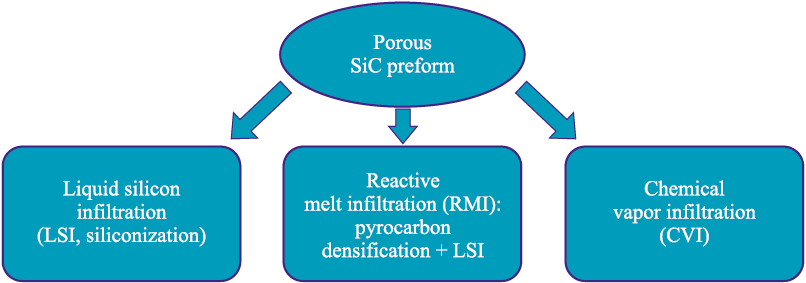
Possible implementations of densification methods for porous SiC preforms are shown in Fig. 1.
Fig. 1. Variants of densification routes for porous SiC preforms |
Chemical vapor infiltration (CVI) involves the infiltration of silane compounds from the gas phase into porous compacts. According to [6], this method yields additively manufactured parts with a bulk density of up to 92 % and a flexural strength of 300 MPa. The residual porosity results from isolated pores that are not accessible from the surface [6].
Siliconization, or liquid silicon infiltration (LSI), is a conventional powder-metallurgy technique used to increase the density of porous graphite and SiC components, thereby minimizing production costs – either by avoiding the need for initially denser compacts or by replacing more time-consuming densification processes. The resulting microstructure contains an increased amount of free silicon, which limits the use of this method by the compositional requirements of the material. During siliconization, pores are filled by molten silicon through capillary action, which increases the density and, consequently, enhances the mechanical properties of the material. Since the mechanical and thermophysical properties of silicon are lower than those of SiC, a drawback of this post-processing method is the reduced overall property set caused by the presence of residual free silicon in the regions formerly occupied by pores.
An important advantage of siliconization is that the process causes virtually no shrinkage. Solidification of molten silicon is accompanied by a volumetric expansion of up to 10.8 % [7], which helps prevent cracking during cooling. This allows the densification of not only simple shapes but also complex-profile parts, where thermal stresses upon cooling are much higher. However, this volume expansion also means that an excess volume is generated during solidification. As the solidification front moves toward the surface, the final freezing of the silicon melt occurs near the surface and is accompanied by expulsion of free silicon outward. This makes mechanical removal of the excess silicon necessary and represents a specific limitation of the method.
Another densification route is the formation of reaction-bonded SiC (RB-SiC) ceramics via reactive wetting of pyrolytic/free carbon by molten silicon within the pores – reactive melt infiltration (RMI) – with the pore space being progressively filled by secondary SiC formed in situ. The process flow is illustrated in Fig. 2. At the first stage, the preform is impregnated with a high-char-yield, low-impurity polymer (e.g., phenolic resin) to fill the pores. The polymer is then thermally decomposed – pyrolyzed – to form pyrolytic carbon in the regions previously occupied by the polymer. Alternatively, a carbon source can be incorporated during the initial preform fabrication, for example by using a mixture of SiC powder with carbon powder.
Fig. 2. Flow diagram of densification of porous SiC part preforms |
Thermal pyrolysis of the polymer binder phase generates internal pressure within the SiC preform due to the active gas evolution associated with the decomposition of organic components in the binder composition. As a result, a thermal cycle with a slow heating rate (about 1–2 °C/h) is required to prevent thermal deformation and cracking during pyrolysis. In this context, geometric limitations are imposed on the resulting components, particularly on the wall thickness. Typically, the binder phase is converted into residual carbon after thermal debinding, but it can directly transform into SiC when a silicon-containing polymer precursor, such as polycarbosilane or allylhydridopolycarbosilane, is used [8].
After binder burnout, a preliminary sintering step is performed to form new and strengthen existing necks between particles, thereby imparting mechanical integrity to the porous body, similar to conventional porous ceramics fabrication.
At the next stage – siliconization – densification occurs through the reaction between the pyrolytic carbon and molten silicon, resulting in the formation of secondary silicon carbide:
| Si(l) + C(s) = SiC(s). | (1) |
The liquid silicon infiltration (LSI) process is typically carried out at 1500–1600 °C. During the exothermic reaction (cementation) between molten silicon and pyrolytic carbon, β-SiC is formed and remains stable upon cooling. It is known that the transformation of β-SiC into α-SiC occurs at temperatures above 2000 °C, although a local thermal spike caused by the exothermic reaction may induce partial conversion to the α modification [9; 10]. Densification is gradually completed during cooling with the formation of a new secondary SiC phase, which coexists with the initial α-SiC, residual free silicon, and, in some cases, unreacted carbon. Depending on its volume fraction, the pyrolytic carbon is either completely or partially converted to SiC during siliconization.
After additional polymer infiltration and pyrolysis (PIP) cycles, the volume fraction of SiC after LSI increases due to the growth of the β-SiC phase on the initial α-SiC particles. The amount of carbon particles decreases as they dissolve in the silicon melt, starting with the smaller ones. The pyrolytic carbon acts as the nucleation center for the formation of the β-SiC phase [11]. The reaction leading to the formation of secondary β-SiC is accompanied by a volumetric expansion of approximately 53 % [12; 13], which exceeds the expansion occurring during the crystallization of silicon in the LSI process.
A variation of the Reactive Melt Infiltration (RMI) method involves using a porous carbon preform instead of SiC for silicon-based densification. The mechanical strength of such products is significantly lower because of the high content of unreacted free carbon (matrix) remaining after siliconization [14].
In the PIP + LSI method, an important parameter affecting the anisotropy of properties is the uniformity of carbon distribution within the pores across the section. This factor determines the completeness of the reaction between free silicon and carbon and, consequently, the residual amount of free silicon. In regions with a higher carbon concentration, the local temperature is elevated, accelerating the C + Si reaction. This, in turn, leads to a pronounced increase in the rates of phase formation and gas evolution (CO and SiO2 ), as well as a rise in the material’s porosity [15].
Another important factor is the carbon content within the pores, defined as the average fraction of a pore’s volume filled with carbon. This parameter determines the infiltration capacity of the pore network during siliconization – that is, how long the molten silicon can penetrate through the system of capillary channels before they become sealed by newly formed SiC. It is crucial to minimize the residual free silicon and porosity to achieve the desired combination of mechanical properties. At the same time, this aspect of the process can be deliberately utilized to fabricate graded materials by varying the porosity, carbon concentration, and free silicon content across the section. The number of PIP cycles directly influences the concentration and distribution of pyrolytic carbon, as well as the amount of residual free silicon. Moreover, the number of infiltration cycles can be optimized to reduce residual porosity and obtain the required mechanical strength characteristics [16].
With an increase in the carbon content of the preform before siliconization, both the strength and density initially rise, reach a maximum, and then decrease. This behavior is explained by the fact that at low carbon contents, a large amount of free silicon remains in the structure, whereas at high carbon contents, free carbon persists, and the pores become sealed, hindering the penetration of silicon into the bulk of the preform. As a result, the interfacial strength between large SiC particles and the residual silicon weakens.
At an optimally adjusted carbon concentration, with appropriate reactivity and pore channel size, the residual pore volume surrounding the pyrolytic carbon can be completely filled with secondary silicon carbide. Thus, the secondary and primary SiC phases can be bonded without residual components in the structure. Reducing the amount of free silicon directly decreases the total area of weak SiC/Si interfaces and the number of regions with localized residual stress concentrations. Consequently, the likelihood of crack initiation along the SiC/Si boundary decreases, while both the density and mechanical strength of the material increase.
The LSI process can also be applied to composites (e.g., Cf /SiC), but it has certain specific features. Since LSI is carried out at a temperature above the melting point of silicon, the carbon fibers (Cf ) eact with molten Si to form SiC [17–19]. This reaction significantly reduces the carbon fiber content in the composite, thereby diminishing the reinforcing effect.
In [20], the CVI method was used to produce a protective SiC interphase coating on the surface of the Cf , preventing their reaction with molten silicon. After LSI processing, the fibers were well protected, and the composite exhibited a flexural strength of 274 ± 13 MPa and a fracture toughness of 5.82 ± 0.25 MPa·m1/2. The authors of [21] fabricated Cf coated with SiC by a hydrothermal method. The SiC coating successfully protected the fibers from erosion and significantly improved the flexural strength and fracture toughness of the Cf /SiC composite by 32.6 and 26.3 %, respectively. However, both of these protective approaches are relatively low in productivity and resource-intensive.
Another study [22] demonstrated that the PIP method can be used to protect fibers prior to siliconization by forming a pyrolytic carbon layer on their surface. This approach is considerably faster and more cost-effective, while increasing the fraction of secondary SiC and reducing the content of free silicon.
The use of various siliconization approaches in combination with SLS offers new opportunities for component fabrication, enabling the production of complex SiC parts with near-net shapes, thereby eliminating the need for costly final machining by additive methods and subsequent densification of porous preforms [23].
The objective of this study was to evaluate the effect of post-processing parameters – polymer infiltration, pyrolysis, and siliconization – on the density of porous SiC preforms produced by the SLS method.
Materials and methods
Porous cubic SiC preforms (10×10×10 mm; Fig. 3) were produced by selective laser sintering in the vertical build direction on mesh supports using a MeltMaster3D-160 system (NPO TsNIITMASH, Moscow) equipped with an ytterbium fiber laser (up to 200 W). The laser energy density used to form the porous SLS preforms was maintained at approximately 100 J/mm3 while varying the layer thickness from 30 to 50 µm according to the following relation:
| \[E = \frac{P}{{Vhd}},\] | (2) |
where Е is the laser energy density, P is the laser power, V and d are the scanning speed and scanning pitch, respectively, and h is the layer thickness.
Fig. 3. Initial porous SLS SiC preforms |
The starting material for sintering was a single-component SiC powder (grade F320), pre-dried at 100 °C. The powder had poor flowability, an average particle size of 48 ± 0.5 µm, a bulk density of 1.11 ± 0.01 g/cm3, and a vibrated density of 1.36 ± 0.01 g/cm3. No sintering aids or other additives were introduced. Layer-by-layer sintering of the SiC powder was carried out in an argon flow atmosphere to prevent oxidation and the formation of SiO2 . The synthesis procedure is described in more detail in [1].
The post-processing of the SLS-fabricated SiC preforms consisted of three main stages:
1. Polymer infiltration – filling the open porosity with a carbon-rich polymer (furan resin). The process was repeated until complete saturation, which was determined by the absence of further mass increase after each infiltration stage.
2. Pyrolysis – thermal decomposition of the polymer with a high carbon yield. After this stage, the infiltrated polymer decomposed within the pore network, leaving free carbon behind. The combined process of polymer infiltration and pyrolysis is referred to as PIP (Polymer Infiltration and Pyrolysis).
3. Siliconization (LSI) – infiltration of the preforms through open porosity with liquid silicon. The process was carried out in a chamber under excess pressure, promoting melt penetration into the pores. The molten silicon reacted with the previously formed free carbon, resulting in the formation of secondary silicon carbide, which crystallized upon cooling. A portion of excess silicon also remained and solidified within the pores, filling them.
The post-treatment aimed at increasing the density and strength of the preforms was carried out using two different methods:
– Liquid Silicon Infiltration (LSI) without preliminary polymer infiltration;
– PIP + LSI, combining polymer infiltration, pyrolysis, and subsequent siliconization.
Polymer infiltration with a carbon-rich precursor
Polymer infiltration was performed in furfurylidene diacetone under vacuum, followed by drying at 150 °C to cure the polymer inside the pores. After each infiltration and curing stage, the preforms were subjected to carbonization (pyrolysis).
Carbonization was carried out in a muffle furnace in air, using a graphite-chip carburizer bed as the protective medium according to the following temperature schedule:
– heating to 240 °C at a rate of 220 °C/h;
– heating to 450 °C at a rate of 20 °C/h;
– heating to 850 °C at a rate of 220 °C/h;
– holding for 1 h;
– cooling to room temperature.
Carbonization of the resin at 850 °C was not complete but sufficient for performing the subsequent operations.
The infiltration procedure was repeated n times until the network of inter-pore channels within the preform volume was saturated. Saturation was evaluated by measuring the specific mass gain after each infiltration cycle. The absence of further weight increase indicated complete saturation of the preform, after which it was subjected to liquid silicon infiltration (LSI). For different preforms, the number of infiltration cycles ranged from 2 to 6.
Siliconization in a vacuum furnace
After completing the infiltration and carbonization cycles, the SLS- preforms were placed in a vacuum thermal furnace for LSI. The preforms were positioned in a crucible on a technological support assembly composed of composite materials and spacer elements. The crucible was placed on a separate stand, taking into account the temperature-field gradient of the furnace hot zone. Pre-prepared silicon was loaded into the crucible. Its quantity was determined by calculation based on the mass of the SLS preform, their free-carbon content, and porosity. LSI was conducted at 1450 °C. Capillary infiltration was used as the mechanism for melt penetration. The temperature was monitored with a pyrometer and visually through the furnace viewing ports. The total process time was about 10 h. After LSI, a small amount of silicon remained on the preform surfaces; the excess was removed mechanically during the finishing step.
Hot mounting of specimens
For metallographic preparation, the specimens were hot-mounted in phenolic resin using a CitoPress-1 mounting press (Struers, Denmark). Mounting was carried out in both longitudinal and transverse orientations relative to the SLS build direction.
Preparation of metallographic specimens
Metallographic specimen preparation was performed in several stages using a TegraPol-11 grinding and polishing system (Struers) equipped with the TegraForce-1 semi-automatic specimen rotation unit (Struers). The preparation sequence included grinding, fine grinding, diamond polishing, and oxide polishing. For grinding, diamond disks with abrasive grain sizes from 54 to 18 µm were used. Running water was supplied continuously to the grinding area as a cooling and lubricating medium. Fine grinding was carried out using composite single-step fine-grinding disks with diamond suspensions of 15–6 µm particle size. Polishing was performed on a hard polishing cloth with 3 µm diamond suspension, followed by final polishing on a soft cloth using an alumina suspension with a particle size of 0.04 µm.
Microscopy
Optical microscopy. Microstructural constituents and their relative proportions in the specimens were examined using an Olympus PNG-3 optical microscope (Japan) equipped with the Vestra Imaging System (NPO LATEMI, Moscow) for image analysis. Quantitative analysis was performed by assigning distinct colors to individual phases and calculating the number of colored pixels using software-based image segmentation.
Because the structural constituents exhibited different etching behavior, chemical etching for microstructure revelation was not performed.
Scanning electron microscopy. SEM studies were conducted using a Tescan Vega 3XMU analytical system (Czech Republic) equipped with an Oxford Advanced AZtec Energy EDS unit (UK) based on an X-Max80 detector (Oxford Instruments, UK). Observations were performed in high-vacuum mode at an accelerating voltage of 20 kV.
Density measurement by hydrostatic weighing
The density of the specimens was determined after SLS fabrication, during post-processing, and after the final LSI stage using the hydrostatic weighing method in accordance with GOST 18898-89. The density was calculated as
| \[\rho = \frac{{{M_1}{\rho _{\rm{c}}}{\rho _{\rm{l}}}}}{{\left( {{M_2} - {M_3}} \right){\rho _{\rm{c}}} - {M_4}{\rho _{\rm{l}}}}},\] | (3) |
where М1 is the mass of the specimen without protective coating, g, М2 is the mass of the coated specimen weighed in air, g, М3 is the mass of the coated specimen weighed in liquid, g, М4 is the mass of the protective coating, g; ρl is the density of the working liquid, g/cm3, ρc is the density of the coating material, g/cm3.
Results and discussion
Post-processing
As a result of post-processing, final SiC specimens were obtained from the porous SLS preforms (Fig. 4). Their outer surface exhibited a characteristic metallic sheen, which can be attributed to the presence of free silicon segregated on the surface. During infiltration, silicon penetrates into the porous SLS preform by a capillary mechanism. It reacts both with the sintered SiC skeleton of the preform and with the free carbon present in the pore channels introduced through the PIP process. Upon crystallization, silicon undergoes volumetric expansion, which causes the residual melt to be expelled toward the surface of the specimens.
Fig. 4. Cubic specimens – porous SLS SiC preforms after PIP |
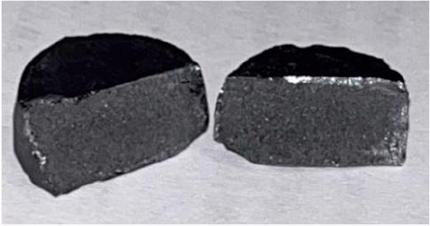
It should be noted that the depth of melt penetration into the bulk is limited by the presence of closed porosity, the pore size, and the reactivity of carbon. Fig. 5 shows a fracture surface of a specimen demonstrating limited melt infiltration to a depth not exceeding 1.0–1.5 mm. In this case, the shallow penetration was associated with an excessive number of PIP cycles, which led to over-saturation with carbon and, consequently, a reduction in pore size and blockage of most pore channels, preventing molten silicon from penetrating into the interior of the porous SLS preform.
Fig. 5. Cross-sectional fracture of a specimen subjected |
The reaction between molten silicon and carbon occurred only in the near-surface zone on all sides of the specimen, since the entire outer surface was in contact with the melt. However, the observed infiltration pattern indicates that the melt penetrated the specimen volume only within this peripheral region, uniformly distributed over the entire cross-section.
Density measurement
The initial density of the specimens fabricated with a layer thickness of 50 µm (hereinafter referred to as “50 µm” specimens) ranged from 1.28 to 1.37 g/cm3, whereas specimens produced with a layer thickness of 30 µm (“30 µm” specimens) exhibited densities 13–16 % higher, in the range of 1.46–1.63 g/cm3. This difference suggests denser layer packing and more complete sintering in thinner layers.
The porous SLS preforms were subjected to PIP densification, which included vacuum infiltration with furfurylidene diacetone followed by carbonization. Carbonization, representing the thermal decomposition (pyrolysis) of the polymer, resulted in the formation of free carbon. After each PIP densification cycle, all specimens were re-weighed to evaluate their density.
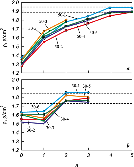
The density data were used to plot density variation curves as a function of the number of PIP cycles (Fig. 6) for preforms fabricated with different technological parameters – namely, layer thicknesses of 50 and 30 µm.
As seen in Fig. 6, a, the initial density increase for the “50 µm” specimens after the first PIP infiltration –from 1.28–1.37 to 1.58–1.67 g/cm3 – amounted to 16–24 %. After the second infiltration, their density rose further to 1.68–1.80 g/cm3, i.e., an additional 7–12 % compared to the first cycle. During subsequent infiltration and pyrolysis cycles, a stable density increase of 2–5 % per cycle was observed.
Fig. 6. Variation in the density (ρ) of specimens treated by |
According to the graphs for the “30 µm” specimens (Fig. 6, b), their density after the first infiltration either remained nearly unchanged or slightly decreased, most likely due to moisture retained in the pores. However, after the second infiltration, the density increased to 1.76–1.85 g/cm3, i.e., by approximately 11–16 % compared to the previous cycle.
A noticeable mass increase for the “30 µm” specimens ceased after the second PIP cycle, while for the “50 µm” specimens it leveled off after the fourth cycle, indicating complete saturation. Thus, the limit of PIP densification was reached after 4–5 cycles for the “50 µm” specimens and after 2–3 cycles for the “30 µm” specimens. Based on the difference in the number of cycles required to achieve saturation for specimens fabricated with different layer thicknesses, it can be inferred that these specimens possess different free volumes and, consequently, different porosities and initial densities, which is consistent with the density measurements. It is also reasonable to assume differences in pore and channel sizes, which could affect pore permeability and infiltration efficiency during polymer infiltration. The final density of the “50 µm” specimens after the last infiltration cycle was 1.88–1.94 g/cm3, while that of the “30 µm” specimens ranged from 1.73 to 1.85 g/cm3.
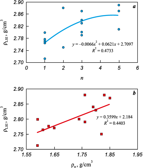
Subsequently, the densified specimens were subjected to liquid silicon infiltration (LSI). Fig. 7 shows the relationship between the density of the “30 µm” specimens after LSI, the number of PIP cycles, and the density after the final PIP cycle.
Fig. 7. Density of the “30 µm” specimens after silicon infiltration (ρLSI ) |
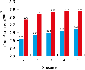
In addition, a comparative analysis of the density of specimens fabricated under identical SLS parameters but subjected to different post-processing routes – LSI only and the combined PIP + LSI treatment – was carried out (Fig. 8). According to the resulting diagram, the specimens after LSI exhibited a density of 2.52–2.65 g/cm3, while those that underwent the complete PIP + LSI cycle reached 2.77–2.88 g/cm3. The average density difference between the specimens after LSI and PIP + LSI treatments was approximately 10 %.
Fig. 8. Comparative density chart of the “50 µm” specimens |
Microstructural studies
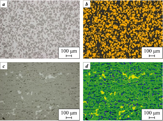
A detailed microstructural analysis was performed on the “50 µm” specimens after both PIP + LSI and LSI treatments to determine the relative contents and distribution characteristics of the SiC, Si, and C phases, as well as residual closed porosity. In the optical micrographs (Fig. 9), the initial SiC powder particles appear as dark gray, irregularly shaped grains, including fragmented and needle-like morphologies. Silicon is observed as light gray regions, while carbon particles appear darker than SiC.
Fig. 9. Microstructure of cross-sections of “50 µm” specimens |
Pores are displayed as black areas. The secondary SiC exhibits an intermediate gray tone between the original SiC and silicon – that is, lighter than SiC grains but darker than free silicon. According to the analysis, the secondary SiC phase is identified similarly to the primary SiC. This is most likely due to the β-SiC → α-SiC transformation, since the resulting α-SiC has a morphology comparable to that of the initial powder.
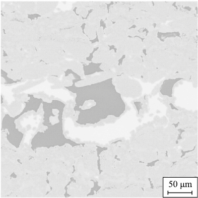
The specimen subjected to the PIP + LSI treatment exhibits a banded structure formed by the distribution of carbon and silicon phases of different shapes and sizes. Carbon and pores are uniformly distributed throughout the specimen cross-section, while silicon is distributed nonuniformly. Relatively large silicon inclusions are localized in regions with high carbon concentration. Evidence of reaction between silicon and carbon with the formation of secondary SiC along the perimeters of these inclusions is observed (Fig. 10). The specimen exhibits both a regular, ordered structure, consisting of repetitive rhombohedral SiC cells surrounded by carbon, and a disordered structure with locally misoriented phases.
Fig. 10. Formation of secondary silicon carbide |
Large carbon inclusions separated by thin silicon veins were concentrated in the peripheral region of the specimen, near the surface, which is likely associated with solidification structure formation under heat dissipation conditions. The specimen also contained numerous continuous, parallel microcracks extending through the structure.
According to the examination of the specimens after LSI, their structures were found to be similar, consisting of uniformly distributed SiC grains embedded in a silicon matrix. The SiC crystals exhibit a regular but non-equiaxed morphology with well-defined grain boundaries. In some regions near the boundaries of SiC grains and within the silicon matrix, fine, diffuse SiC precipitates were observed.
The structure of all LSI specimens is dense, containing only isolated pores located mainly within the SiC phase. Across all specimens, sharp-edged recesses of regular shape were found. These features likely originated from the pull-out of SiC or other hard-phase crystallites during metallographic preparation.
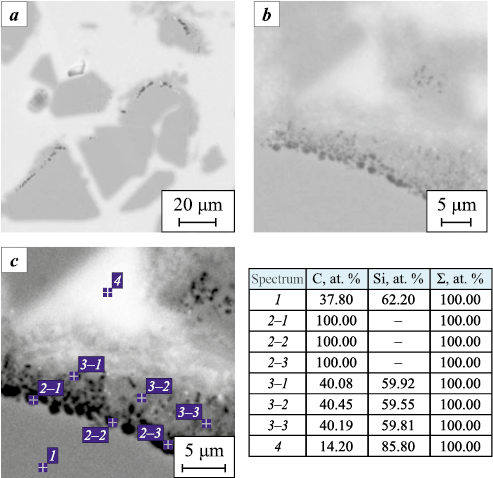
Detailed SEM analysis of the SiC phase revealed the presence of graphitic inclusions within individual SiC grains (Fig. 11). These inclusions appear as chains of point-like features localized along the grain boundaries of the carbide crystals.
Fig. 11. Carbon-phase inclusions within the SiC phase |
The Table below presents the quantitative contents of SiC, free Si, and carbon phases in the specimens after PIP + LSI and LSI treatments. The contents of pores and the carbon phase in the LSI-treated specimen were not considered in the calculation because of their negligibly small amount (<1 %).
Proportions of structural constituents
| |||||||||||||||||||||||||
Based on the data in the Table, it can be concluded that the specimens without preliminary PIP treatment contain approximately 50 % less SiC phase than those subjected to the full PIP + LSI cycle. This difference may be attributed both to the lower density of the initial preforms and to the absence of secondary SiC formation. From the difference in the SiC content between the LSI and PIP + LSI specimens, it can be inferred that the secondary SiC phase (SiCII ) forms in the amount of 25–37 %, increasing the total SiC content in the material from 43–45 to 70–80 %. This increase likely enhances both the mechanical and thermophysical properties of the material. At the same time, the porosity of the LSI specimens was found to be quantitatively lower, which can be explained by better capillary penetration of the silicon melt into the bulk due to larger pore sizes and the absence of pore-channel blockage by carbon. According to the microstructural images, the additional porosity observed in the PIP + LSI specimens may be associated with incomplete wetting of large residual carbon inclusions and the formation of voids at the interface with the free silicon phase, resulting in localized porous zones.
Based on the obtained quantitative phase composition, it can be assumed that the LSI specimen, with a SiC content of 43–45 %, would be expected to have a theoretical density of 2.70–2.73 g/cm3 instead of the actual 2.52–2.65 g/cm3, while the PIP + LSI specimen, containing 70–80 % SiC, should theoretically reach 2.94–3.03 g/cm3 instead of the measured 2.77–2.88 g/cm3. However, the lower actual density values indicate the presence of additional low-density phases and residual porosity, both of which affect the overall result – findings that are consistent with the quantitative microstructural analysis.
Further research aimed at optimizing the post-processing parameters to achieve maximum densification of SLS SiC preforms and evaluating the mechanical properties will help establish a correlation between the mechanical strength and the quantitative phase composition of the final specimens after different post-processing routes. Planned future studies also include mechanical testing to determine the fracture mechanisms of specimens fabricated along different build directions, in order to assess the possible anisotropy of mechanical properties.
Conclusions
1. The initial density of the specimens fabricated by SLS was 15–30 % higher than the bulk density of silicon carbide. For the “50 µm” specimens, the density was comparable to that of vibratory-compacted powder, while the “30 µm” specimens exhibited densities 10–15 % higher than that of vibratory-compacted powder. The SiC powder particles had irregular (elongated) shapes. To achieve higher final density, it is necessary to increase the initial preform density, for example, by using more spherical SiC powder.
2. The increase in the initial density of the SLS preforms with decreasing layer thickness is likely associated with improved vertical heat transfer in thinner layers (30 µm). This thermal profile promotes particle sliding/rearrangement, reduces interparticle pore size, and improves adhesion to the previously sintered layer. In contrast, for 50 µm layers the packing density may decrease because of a double-layer effect: two needle-like SiC particles can stack vertically, leading to additional heat absorption (thermal shielding) and difficulty achieving full, uniform heating during laser sintering. Consequently, interlayer sliding and consolidation proceed less efficiently than in the “30 µm” specimens, where each layer is approximately one particle thick. In the “50 µm” specimens, the initial density was 1.3–1.4 g/cm3, whereas in the “30 µm” specimens, it reached 1.5–1.6 g/cm3.
3. The SLS specimens can be densified by polymer infiltration and pyrolysis (PIP) to a density of 1.85–1.94 g/cm3, indicating a carbon mass uptake of up to 0.62 g/cm3 – sufficient for the subsequent formation of secondary SiC within the pores, thereby increasing the overall density toward the theoretical value.
4. Comparison of the densities of specimens subjected to PIP + LSI treatment shows a linear correlation, indirectly confirming a high degree of carbon conversion into secondary SiC and demonstrating the potential for further material quality improvement. The quantitative microstructural analysis directly supports this conclusion, showing that the secondary SiC (SiCII ) accounts for 25–37 % of the total SiC content.
5. It is necessary to optimize both the amount and reactivity of carbon introduced into the SLS preforms, as well as the method of its incorporation, to achieve maximum final density with minimal porosity. Introducing excess carbon (to generate more than ~35 % of secondary SiC) results in high residual carbon content and significant closed porosity due to pore-channel blockage during infiltration and pyrolysis. Improved results may be obtained by modifying the polymer precursor or by using alternative infiltration polymers.
6. The “30 µm” specimens achieved maximum carbon densification after only 2–3 infiltration cycles, while the “50 µm” specimens required 4–5 cycles. This difference can be attributed to variations in total porosity and pore-channel cross-section size, which affect the saturation efficiency during infiltration.
7. The final density after siliconization (LSI) was insufficient for both the “50 µm” and “30 µm” specimens. The maximum achieved density was 2.88 g/cm3. The specimens subjected to only one PIP infiltration showed the lowest post-LSI density (2.62–2.80 g/cm3). To reach maximum densification, 4–5 infiltrations are required for the “50 µm” specimens, and 2–3 for the “30 µm” specimens.
8. The results demonstrate that SLS-fabricated specimens subjected to LSI without preliminary PIP treatment exhibit lower density (2.52–2.65 g/cm3) compared to those that underwent the full PIP + LSI process (2.62–2.88 g/cm3). In earlier experiments with infiltration, visible voids and delaminations were observed, whereas in the present specimens no delaminations or large pores were detected, confirming improved structure integrity.
References
1. Bubnenkov B.B., Zharmukhambetov A.S., Ivanov I.A., Yudin A.V., Taktashov A.E., Starkov A.M., Sharapov I.S., Alekseeva E.M. Investigation of influence of technological parameters on the properties of SiC samples fabricated by selective laser sintering. Part 1. Powder Metallurgy аnd Functional Coatings. 2024;18(3):71–84. https://doi.org/10.17073/1997-308X-2024-3-71-84
2. Bubnenkov B.B., Zharmukhambetov A.S., Ivanov I.A. Methods of additive technologies for the manufacture of silicon carbide products. Part 1. Tyazheloe mashinostroenie. 2024;(10):2–9. (In Russ.).
3. Bubnenkov B.B., Zharmukhambetov A.S., Ivanov I.A. Methods of additive technologies for the manufacture of silicon carbide products. Part 2. Tyazheloe mashinostroenie. 2024;(11-12):2–11. (In Russ.).
4. Hutchins O. Method of producing silicon-carbide articles: Patent 1266478 (USA). 1918.
5. Popper P., Davies D.G.S. The preparation and properties of self-bonded silicon carbide. Powder Metallurgy. 1961;4(8):113–127. https://doi.org/10.1179/pom.1961.4.8.009
6. Terrani K., Jolly B., Trammell M. 3D printing of high-purity silicon carbide. Journal of the American Ceramic Society. 2020;103(3):1575–1581. https://doi.org/10.1111/JACE.16888
7. Faes M., Valkenaers H., Vogeler F., Vleugels J., Ferraris E. Extrusion-based 3D printing of ceramic components. Procedia CIRP. 2015;28:76–81. https://doi.org/10.1016/j.procir.2015.04.028
8. Baux A., Goillot A., Jacques S., Heisel C., Rochais D., Charpentier L., David P., Piquero T., Chartier T., Chollon G. Synthesis and properties of macroporous SiC ceramics synthesized by 3D printing and chemical vapor infiltration/deposition. Journal of the European Ceramic Society. 2020;40(8):2834–2854. https://doi.org/10.1016/j.jeurceramsoc.2020.03.001
9. Baumann H.N. The relationship of alpha and beta silicon carbide. Journal of the Electrochemical Society. 1952;99(3):109. https://doi.org/10.1149/1.2779671
10. Seo Y.K., Eom J.H., Kim Y.W. Process-tolerant pressureless-sintered silicon carbide ceramics with alumina-yttria-calcia-strontia. Journal of the European Ceramic Society. 2018;38(2):445–452. https://doi.org/10.1016/j.jeurceramsoc.2017.09.011
11. Oh J-W., Park J., Nahm S., Choi H. SiC–Si composite part fabrication via SiC powder binder jetting additive manufacturing and molten-Si infiltration. International Journal of Refractory Metals and Hard Materials. 2021;101: 105686. https://doi.org/10.1016/j.ijrmhm.2021.105686
12. Logan R.A., Bond W.L. Density change in silicon upon melting. Journal of Applied Physics. 1959;30(3):322. https://doi.org/10.1063/1.1735159
13. Zhou H., Singh R.N. Kinetics model for the growth of silicon carbide by the reaction of liquid silicon with carbon. Journal of the American Ceramic Society. 1995;78(9):2456–2462. https://doi.org/10.1111/j.1151-2916.1995.tb08685.x
14. Markov M.A., Krasikov A.V., Kravchenko I.N., Erofeev M.N., Bykova A.D., Belyakov A.N. Development of new structural ceramic materials based on silicon carbide for products with complex geometry. Problemy mashinostroeniya i nadezhnosti mashin. 2021;(2):81–87. (In Russ.). https://doi.org/10.31857/S0235711921020097
15. Xu H., Liu Y., Che Y., Chen Z. Combination of direct ink writing and reaction bonded for rapid fabrication of SiCw/SiC composites. Ceramics International. 2023;49(1): 392–402. https://doi.org/10.1016/j.ceramint.2022.09.002
16. Cramer C.L., Elliott A.M., Lara-Curzio E., Flores-Betancourt A., Lance M.J., Han L., Blacker J., Trofimov A.A., Wang H., Cakmak E., Nawaz K. Properties of SiC–Si made via binder jet 3D printing of SiC powder, carbon addition, and silicon melt infiltration. Journal of the American Ceramic Society. 2021;104(11):5467–5478. https://doi.org/10.1111/JACE.17933
17. Hozer L., Lee J.-R., Chiang Y.-M. Reaction-infiltrated, net-shape SiC composites. Materials Science and Engineering: A. 1995;195:131–143. https://doi.org/10.1016/0921-5093(94)06512-8
18. Narayan J., Raghunathan R., Chowdhury R., Jagannadham K. Mechanism of combustion synthesis of silicon carbide. Journal of Applied Physics. 1994;75:7252–7257. https://doi.org/10.1063/1.356660
19. Tang J., Liu M., Wei Y., Yang Y., Huang Z. An efficient and low-cost liquid silicon infiltration method to prepare SiC-coated carbon short fiber for fiber protection of Cf/SiC ceramic matrix composites. Ceramics International. 2021;47(9):13235–13241. https://doi.org/10.1016/j.ceramint.2021.01.115
20. Lu Z., Xia Y., Miao K., Li S., Zhu L., Nan H., Cao J., Li D. Microstructure control of highly oriented short carbon fibres in SiC matrix composites fabricated by direct ink writing. Ceramics International. 2019; 45(14):17262–17267. https://doi.org/10.1016/j.ceramint.2019.05.283
21. Zhang H., Yang Y., Liu B., Huang Z. The preparation of SiC-based ceramics by one novel strategy combined 3D printing technology and liquid silicon infiltration process. Ceramics International. 2019;45(8):10800–10804. https://doi.org/10.1016/j.ceramint.2019.02.154
22. Hu S., Feng K., Wang Q., Sun J., Yuan J., Mao Y., Cai D., Jiang W., Ye C., Wei Q. Lightweight Cf/SiC composites with high fiber content fabricated by binder jetting additive manufacturing and liquid silicon infiltration. Additive Manufacturing Frontiers. 2024;3(1):200116. https://doi.org/10.1016/j.amf.2024.200116
23. Zocca A., Lima P., Diener S., Katsikis N., Günster J. Additive manufacturing of SiSiC by layerwise slurry deposition and binder jetting (LSD-print). Journal of the European Ceramic Society. 2019;39(13):3527–3533. https://doi.org/10.1016/j.jeurceramsoc.2019.05.009
About the Authors
B. B. BubnenkovRussian Federation
Bogdan B. Bubnenkov – Research Scientist, Institute of Metallurgy and Mechanical Engineering (IMME)
4 Sharikopodshipnikovskaya Str., Moscow 115088, Russia
A. S. Zharmukhambetov
Russian Federation
Alps S. Zharmukhambetov – Head of the Laboratory of Additive Technologies, IMME
4 Sharikopodshipnikovskaya Str., Moscow 115088, Russia
I. A. Ivanov
Russian Federation
Ivan A. Ivanov – Cand. Sci. (Phys.-Math.), Associate Professor, Director of IMME
4 Sharikopodshipnikovskaya Str., Moscow 115088, Russia
I. S. Sharapov
Russian Federation
Ilya S. Sharapov – Deputy Director of the Department
24 Zheleznodorozhnaya Str., Podolsk, Moscow region 142103, Russia
S. N. Veselkov
Russian Federation
Sergey N. Veselkov – Leading Engineer
24 Zheleznodorozhnaya Str., Podolsk, Moscow region 142103, Russia
Review
For citations:
Bubnenkov B.B., Zharmukhambetov A.S., Ivanov I.A., Sharapov I.S., Veselkov S.N. Densification of porous SLS SiC preforms through polymer infiltration, pyrolysis, and liquid silicon infiltration. Powder Metallurgy аnd Functional Coatings (Izvestiya Vuzov. Poroshkovaya Metallurgiya i Funktsional'nye Pokrytiya). 2025;19(5):80-93. https://doi.org/10.17073/1997-308X-2025-5-80-93


