Scroll to:
Transformation of the nickel aluminide alloy structure through the application of a heat-resistant coating using oscillation electrode surfacing
https://doi.org/10.17073/1997-308X-2023-4-59-70
Abstract
This study considers the formation of an alloyed nickel aluminide structure through automatic electric arc surfacing employing an oscillating electrode composed of composite wire. The arc transversely traverses the weld pool surface at a frequency denoted as f. In comparison to conventional surfacing techniques, this process either displaces the crystallization front alongside the weld pool (at f = 1.3 Hz) or stabilizes it (at f ≥ 2 Hz) throughout the cross-sectional area of the coating layer. We have conducted an investigation into the evolution of alloy structures resulting from surfacing. Notably, we have observed that the regions with concentrations of eutectic nickel-aluminum are particularly susceptible to structural alterations. The formation of particle clusters, which is contingent upon heat dissipation conditions near the crystallization front, leads to the development of layered texture regions. Our findings reveal that following 50 thermal cycles (heating to 1100 °C, cooling to 25 °C), the alloy's hardness becomes independent of subsequent thermal cycles, consistently maintaining a level 34–35 HRC. The highest resistance of the surfaced metal to thermal fatigue cracks is achieved when its structure exhibits an optimal γ-solid solution (relatively ductile) to nickel-aluminum cooling martensite ratio, corresponding to the Ni2Al phase. The thermal conditions necessary for producing such a structure are elucidated by the gradual cooling of the crystallized metal from elevated temperatures when f ≥ 2.8 Hz. An analysis of changes in oxidative wear, estimated by mass loss, during thermal fatigue tests conducted at a metal heating temperature of 1100 °C revealed the superiority of the studied alloy over industrial alloys based on nickel and cobalt.
Keywords
For citations:
Zorin I.V., Lysak V.I., Kharlamov V.O., Fastov S.A. Transformation of the nickel aluminide alloy structure through the application of a heat-resistant coating using oscillation electrode surfacing. Powder Metallurgy аnd Functional Coatings (Izvestiya Vuzov. Poroshkovaya Metallurgiya i Funktsional'nye Pokrytiya). 2023;17(4):59-70. https://doi.org/10.17073/1997-308X-2023-4-59-70
Introduction
Developed during the mid-20\(^{\rm{th}}\) century, weld overlay represents an efficient technique for extending the operational lifespan of products exposed to temperatures as high as 1000 °C. To enhance the resistance of the cladding layer against high-temperature wear, iron, nickel, and cobalt alloys are commonly employed [1‒3]. These alloys have undergone extensive research. Conversely, nickel aluminide-based heat-resistant alloys for surfacing have garnered substantial practical interest. Among these, Ni3Al and NiAl intermetallics are particularly promising [4; 5].
Both domestic and international nickel aluminide casting alloys exhibit improved thermal stability [4; 6], elevated high-temperature and fatigue strength [7; 8], and resistance to high-temperature oxidation [4; 9]. Despite the significant potential of these alloys, their application in cladding is constrained due to the high sensitivity of nickel aluminide to heating and cooling rates, primarily owing to the elevated γ′-Ni3Al phase content, which diminishes plasticity and hinders stress relief during welding [10]. Consequently, it is imperative to maintain a low-temperature gradient at the crystallization front in the weld pool. Meng Zhang et al. [11] have reported achieving a similar outcome by constructing a vertical “wall” of Ni3Al alloy via a multilayer weld overlay technique under argon shielding, incorporating multiple reheating cycles by subsequent layers, and controlling the cooling rate (1‒2 °C/s).
In contrast to the “gentle” thermal deformation cycle of argon arc surfacing using a non-consumable electrode, semi- or fully automated weld overlay employing a consumable electrode significantly enhances both productivity and the quality of the surfacing layer. However, as highlighted by Sorokin L. et al. [12], the conditions for metal structure formation become more complex due to the higher heat input and the larger melt pool volume, resulting in increased weld stress [12].
Various methods are currently employed to control heat input during welding processes. These methods encompass the use of pulse [13] and modulated [14] weld current, high-frequency oscillations of the electrode [15], or, as the most common and cost-effective approach, adjusting the specific welding energy. The control of specific energy can influence the size and shape of the weld pool and, consequently, the properties of the surfacing metal in the clad alloy. However, this control is effective only within specific ranges of welding arc power and weld deposit rates [16], which are contingent on the particular alloying system [17; 18]. For Ni–Cr cladding, a relatively wide range of weld overlay rates can be applied to manage phase composition and structure size while ensuring a defect-free surfacing layer. Nevertheless, for high-carbon and boron-containing wear-resistant alloys, the applicable range of rates is considerably narrower.
Several strategies have been devised to minimize the conversion of weld energy into heat input at the crystallization front. Wu Dongting et al. [19] suggested excluding the workpiece from the welding circuit. Another method involves employing transverse oscillations of the weld arc across the weld pool surface. This latter approach to heat input control offers greater flexibility and was originally investigated by G.G. Chernyshev, B.N. Kushnirenko, and M.M. Shtrikman in the 1960s and 1970s. Today, it finds application in multilayer wear-resistant surfacing [20]. Pre-eutectic and eutectic wear-resistant alloys with high chromium and carbon content exhibit more favorable responses to transverse electrode oscillations with specific frequencies and amplitudes [17; 21; 22]. In certain instances, repeated thermal effects are applied to the crystallizing metal as the weld arc moves, potentially altering the carbide phase morphology and grain size [23]. It has been postulated that utilizing an oscillating electrode for cladding an alloy containing eutectic phases of nickel aluminide is a preferred approach for controlling the thermal conditions of structure formation, thereby enhancing the thermal resistance of the surfacing layer.
The primary objective of this study is to characterize the structure of the nickel aluminide alloy formed during surfacing under the influence of repeated thermal effects on the cladding layer.
Materials and Methods
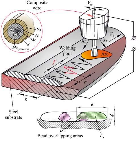
We employed electrodes crafted from composite wire (CW) with a diameter of 3 mm. This wire was manufactured through a 6-pass drawing process using a carbide die. The wire sheath consists of a nickel strip, while the wire filler comprises aluminum, tungsten, molybdenum, powdered tantalum, and chromium. This composite wire design (Fig. 1) ensures a uniform distribution of filler components along the length of the wire. In the case of powder wires, achieving such uniformity typically requires a layer-by-layer arrangement of filler components possessing similar physical and mechanical properties. The inherent inhomogeneity in thermophysical properties across the cross-section is a common characteristic of composite structures, yet this is mitigated by effective electrical contact between the surfaces of the composite wire components, facilitating rapid heating. Taking into account the loss of filler elements due to oxidation within the weld pool, the theoretical composition of the composite wire corresponds to a stoichiometric nickel-to-aluminum mass ratio ~6.5. The inclusion of refractory alloying elements such as tungsten, molybdenum, and tantalum in the filler material strengthens the γ′-solid solid solution and enhances the stability of the γ’-phase at temperatures up to 1100 °C. Additionally, the surfacing layer contains a minimum of 4 wt. % chromium, which, when combined with aluminum, imparts robust resistance to high-temperature oxidation. As a substrate, we utilized plates measuring 12×80×170 mm, composed of the 5CrNiMn steel grade.
Fig. 1. Cladding process |
The resulting chemical composition (wt. %) of the nickel aluminide alloy is as follows:
Ni . . . . . . . . Base metal W . . . . . . . . . 3.3–3.6
C . . . . . . . . . 0.2–0.3 Mo . . . . . . . . 2.6–3.1
Al . . . . . . . . 8.2–8.5 Ta . . . . . . . . . 2.3–2.5
Cr . . . . . . . . . 4.0–4.2 Fe . . . . . . . . . 12–15
Equally spaced VP 5/20 tungsten alloy thermocouples were installed within the steel substrate at depth of 1.5 mm below the surface. These thermocouples are designed to gauge the temperature at the base of the weld pool and in close proximity to the crystallization front as the base metal undergoes melting. The thermocouples were constructed using 0.6 mm diameter wire. In order to process the thermocouple signals, we utilized an LA-20USB multichannel ADC converter from Rudnev–Shilyaev, Moscow, and subsequently transferred the data to a PC. The PowerGraph™ software was employed to record the signals and generate temperature vs. time curves.
The melting point of the alloy, as determined by differential scanning calorimetry, is ~1386 °C. In order to further investigate the structure and elemental composition of the alloy, we employed an electron-ion microscope (FEI Versa 3D, USA).
In order to assess the cladding layer’s resistance to thermal fatigue cracking, we conducted cyclic heating tests and monitored the number of heating-cooling cycles until the first fatigue cracks became evident. The samples, measuring 15×15×4 mm, consisted of single-layer cladding metal. Additionally, we fabricated test samples using Stoodite 6 and Hastelloy C clad alloys. These samples were then positioned within a furnace that was heated to a temperature of t = 1100 °C, held at this temperature for 6 min, and subsequently cooled down to t = 25 °C in 7–9 s. This testing protocol encompassed a total of 240 thermal cycles. In order to evaluate the oxidation resistance of the samples, we measured the mass loss of each sample after every 30 thermal cycles. These measurements were carried out using a VIBRA HT-124RCE analytical balance (Shinko Denshi Co. LTD, Japan) with a readability of 0.1 mg.
Surfacing Process
We employed an A2 Mini Master welding machine (ESAB, Sweden), which includes an electrode oscillation drive. The electrode oscillates transversely to the direction of the cladding. The oscillation drive converts the rotation of the gearmotor shaft into a reciprocating rectilinear motion of the lever connected to the electrode wire feeder. The velocity of the transverse oscillations of the electrode Vto spans from 16 to 50 mm/s. This velocity decreases to approximately 0.1 times Vto at the extremities of the electrode’s oscillation amplitude (b).
The transverse oscillation velocity is synchronized with the linear surfacing velocity (Vs ). Consequently, the surfacing increment (h) is automatically chosen by the welding machine to maintain the specified Vs value. An increase in Vto to ~50 mm/s results in a decrease in surfacing increment, causing the arc to reach the end of its transverse path within 1 s, and the oscillation frequency (f ) approaches 3 Hz. Conversely, when Vto is reduced to 16 mm/s, the surfacing increment increases, and f shifts to its minimum value of ~1 Hz (see Fig. 1).
We introduced the weld bead shape factor (µb ), defined as the ratio of the cross-sectional area of the bead to the area of a rectangle with dimensions equal to the bead width (e) and bead height (g) (see Fig. 1). For single-layer coatings, the bead-to-bead overlap varied in the range of 30–50 %, depending on µb. The steel substrate comprises 16–20 % of the surfacing layer.
In order to ensure superior weld bead quality, the surfacing velocity was set at 19 cm/min. Exceeding this value adversely affects the weld beads, resulting in inconsistencies in their shape, length, and width. As the surfacing velocity decreases (<10 m/h), the retraction of molten material into the tail of the weld pool is significantly reduced, leading to an expansion of the weld pool volume beneath the arc. This results in a shorter arc and disrupts the wire melting process. Arc stability (preventing short circuits in the arc gap with the refractory wire filler) is achieved at Uarc = 27 V. A welding current of Iweld = 280 ± 15 A was selected to provide the arc thermal power sufficient to melt the refractory filler in the wire while preventing overheating of the drop at the wire end. Initially, the heat needed to keep the filler components in a molten state is supplied by the anode spot at the end of the refractory tungsten-molybdenum filler. When the melt entirely covers the refractory filler, the anode spot shifts to the end surface of the resulting drop. The drop separates as it descends along the surface of the partially molten filler. Following this, a new molten filler drop begins to form around it [24].
The welding current source (DC, reversed polarity) utilized was an LAF 1001 thyristor rectifier (ESAB, Sweden). The primary surfacing process variables include:
|
Results and discussion
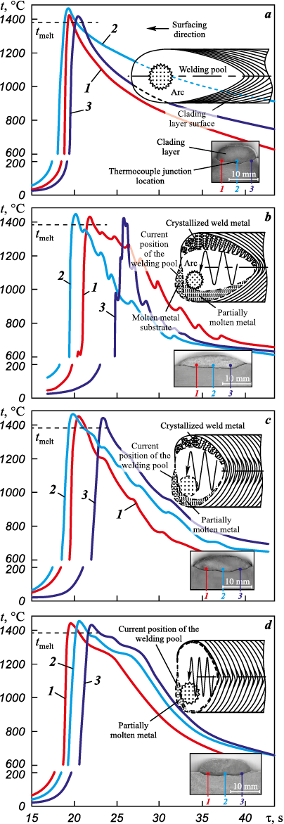
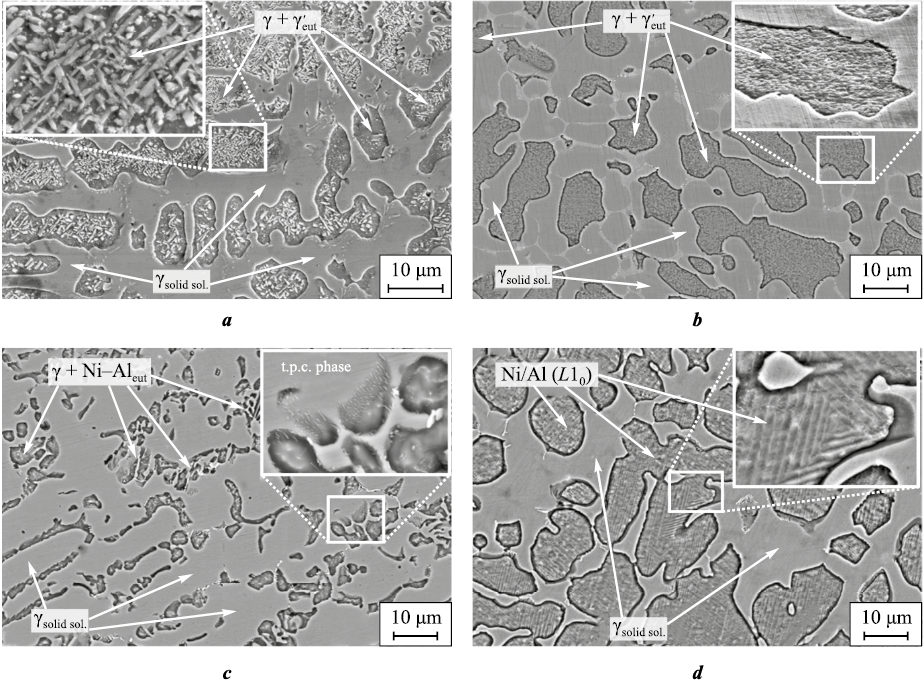
The analysis of the metal’s heating and cooling profile during arc cladding without transverse composite wire oscillations reveals a thermal cycle with a single peak (Fig. 2, a). This peak corresponds to the maximum temperature reached when the melt contacts the thermocouple junction. During the cooling stage near the crystallization temperature, the cooling rate is relatively high (~100 °C/s). Subsequently, starting from 1300 °C, the temperature decrease gradually slows down to ~20 °C/s. The resulting structure of the cladding layer, formed under such non-equilibrium conditions (Fig. 3, a), comprises two regions with roughly equal volume fractions. One of these regions consists of the alloyed γ-solid solution, characterized by primary crystallizable dendrites. The other region contains dispersed lamellar particles of the γ′-phase. As per the established concept of the Ni3Al alloy structure and phase state, based on the work of Kolobov Yu. et al. [4], these particles are formed through the L ↔ γ + γ′ eutectic reaction.
Fig. 2. Thermal cycles of the surfacing process without (a)
Fig. 3. Structures of the alloys surfaced without (a) and with electrode oscillations (b–d) |
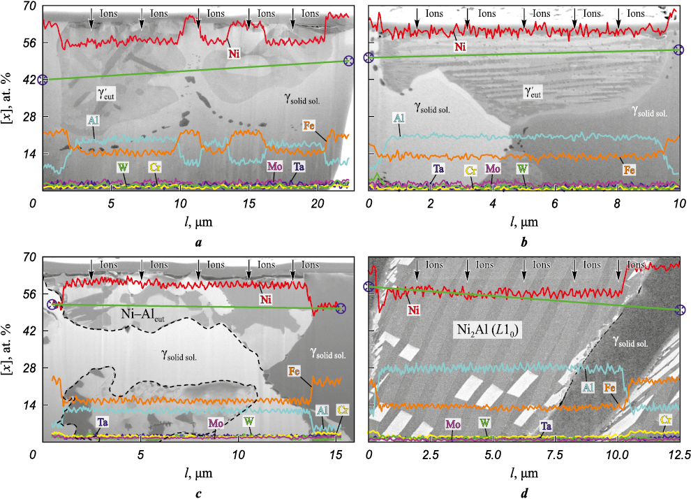
Further analysis of the eutectic concentration areas reveals significant non-uniformity in the distribution of iron and aluminum between the two primary phases. The eutectic nickel-aluminum areas exhibit the highest concentrations of aluminum and nickel (Fig. 4, a, b). Given that iron can form a continuous solid solution with nickel, it is primarily dissolved in the γ-phase. The presence of iron in the γ′-phase can be attributed to its ability to substitute for both nickel and aluminum in Ni3Al.
Fig. 4. Structure and elemental composition of the eutectic concentration areas after ion “etching” |
The transverse oscillations of the electrode (at a frequency of f = 1.3 Hz) lead to the appearance of multiple peaks on the cooling curve (see Fig. 2, b). These peaks correspond to short-term temperature fluctuations caused by reheating of the cooled metal by the arc. The pattern of the peaks for 1, 2 and 3 thermal cycles indicate that the crystallizing metal experiences elevated temperatures for a limited duration. This phenomenon arises due to the cyclic redistribution of hot and cold areas within the weld pool as the pool moves in response to the transverse oscillations of the weld arc. However, when the weld pool tracks the heat source (the arc), it remelts the previously cooled metal, and crystallization recommences. This cyclic process results in a chaotic orientation of crystallite growth and the interweaving of crystallites, as observed in the lower and partially middle sections of the beads. The structure of the upper (working) bead (Fig. 3, b) displays a high degree of dispersion within the regions containing the eutectic γ′-phase. The size of such regions does not exceed 20 μm. The γ-solid solution areas contain small fractions of segregations, likely consisting of topologically close-packed (TCP) phases.
The morphological alterations within the γ′-phase induce a transformation from lamellar and sharply-angular particle clusters (typically found in alloys produced without electrode oscillations, Figs. 3, a and 4, a) into layered texture regions when oscillations occur at f = 1.3 Hz. Each layer within these regions exhibits a distinct crystallographic orientation. The weld bead created with an oscillating electrode is notably wider, ranging from 150 % to 170 % wider (as shown in Fig. 2, b), yet its µb value (0.72 < 0.88) is lower in comparison to the bead produced without oscillations.
Increasing frequency f to 2 Hz results in the anticipated reduction of both the weld pool and crystallization front lengths. This is corroborated by more similar heating and cooling curves observed at the thermocouple locations. The cooling rate decelerates, and the temperature peaks resulting from repeated heating due to arc oscillations become less pronounced (Fig. 2, c). These changes lead to the predominance of the γ-solid solution in the structure, with these regions interspersed by areas containing fragmented eutectic nickel-aluminum (Fig. 3, c and Fig. 4, c). The nickel-to-aluminum ratio in these regions falls below the stoichiometric ratio required for the formation of the γ′-Ni3Al-phase (Fig. 4, c). The weld bead formed at f = 2 Hz exhibits a slightly higher weld bead shape factor (0.75) while maintaining a comparable width.
Further increase of the arc oscillation frequency to f = 2.8 Hz results in the smoothing of the temperature peaks caused by reheating in the cooling curves (as observed in Fig. 2, d) and shortens the time intervals between these peak temperatures. This phenomenon suggests a more uniform temperature gradient across the width of the weld pool. Simultaneously, the weld pool length decreases, while its volume increases due to the rapid transverse oscillations of the arc at approximately ~44 mm/s. Consequently, the weld bead becomes even wider (µb = 0.82) (Fig. 2, d), in comparison to beads produced at at lower f.
At an oscillation frequency of f = 2.8 Hz, the conditions governing heat input to the crystallization front change, resulting in an extended period during which the crystallizing metal is at the nickel aluminide melting point (Fig. 3, d). In such conditions, the formation of the structure initiates with the emergence of alloyed γ-solid solution dendrites and concludes with the appearance of nickel-aluminum martensite (L10 lattice) in the phase diagram region situated between the γ′-phase and the β-(NiAl)-phase. The primary reason for this martensite formation is the relatively slow cooling rate of the nickel-aluminum alloy from temperatures below 1200 °C, in contrast to the cooling rate typical of lower frequencies in non-oscillatory surfacing. A similar hypothesis was put forth by Kositsyn S. et al. [25]. Prolonged exposure of the metal to elevated temperatures results in annealing. Prior to the formation of cooling martensite, the alloy’s composition undergoes modification: it becomes enriched with aluminum atoms, which, as indicated by Kablov D. et al. [26], exhibit the highest diffusion coefficient in nickel (in the context of the alloying system under consideration) at temperatures exceeding 900 °C. This shift in composition moves the alloy towards the region where the β-phase is stable. Examination of the martensitic region following surface ion etching reveals the presence of relatively thin plates (measuring 300–600 nm) with twinning orientation relative to each other (as depicted in Fig. 4, d). The atomic mass ratio of nickel to aluminum corresponds to that of the Ni2Al phase.
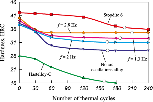
The alteration in the metal’s structure due to transverse weld arc oscillations has an impact on its hardness, which varies within the range of 27 to 35 HRC depending on the oscillation frequency. It’s worth noting that after ~50 thermal cycles (Fig. 5), the hardness of the alloy deposited at f = 2.8 Hz no longer depends on subsequent thermal cycles. It remains constant, which can be attributed to the overall high thermal stability of the alloy structure.
Fig. 5. Alloy hardness vs. number of thermal cycles |
The alloy surfaced at f = 2.8 Hz exhibits the highest hardness value (~35 HRC), whereas the lowest hardness (27 HRC) is observed in the surfacing conducted without transverse arc oscillations (see Fig. 5). Under identical test conditions, the hardness of the commercially available Ni alloy Hastelloy C steadily decreases due to its progressive softening and loss of thermal stability.
The cobalt-based alloy Stoodite 6, characterized by a slightly higher initial hardness of 42 HRC, demonstrates robust resistance to softening. It retains its hardness almost consistently for up to 100 thermal cycles. With a further increase in the number of thermal cycles, the hardness gradually decreases and approaches the level of approximately 35 HRC, which is similar to the hardness of the alloy manufactured at f = 2.8 Hz.
The results of thermal fatigue tests indicate that the alloy produced at 2.8 Hz exhibits the highest durability, enduring for up to 200 cycles (Fig. 5). This durability can be attributed to the attainment of an optimal ratio between the γ-solid solution and nickel-aluminum cooling martensite within the structure of a relatively ductile metal. This metal is highly alloyed, containing up to 18 wt. % of iron and other elements. Au Y. et al. [27] reported that such an alloy is susceptible to thermoelastic transformations. During the tests, reheating of the martensite restored the reversibility of the martensite transformation. However, subsequent multiple thermal cycles lead to the dispersive decomposition of the metastable Ni2Al-phase into Ni5Al3-phase particles and a decrease in the critical temperatures of the martensitic transformation. The tungsten and tantalum contents in the examined alloy do not significantly differ, whereas chromium and molybdenum are primarily dissolved in the γ-solid solution.
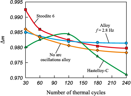
The assessment of oxidative wear resulting from thermal fatigue tests indicates that the studied alloy, manufactured at f = 2.8 Hz, exhibits superior properties compared to other available heat-resistant materials after 125 thermal cycles (Fig. 6). This difference is particularly pronounced when compared to Hastelloy C, which displays lower oxidation resistance. The diminished oxidation resistance of Hastelloy C can be attributed to the increased diffusion of oxygen from the oxidizing atmosphere through the Cr2O3 oxide layer. In contrast, the elevated chromium content in the alloy forms a barrier that initially hinders oxygen diffusion during the test. This barrier thickens over the course of 100–110 thermal cycles (Fig. 6). Subsequently, the protective layer experiences partial degradation.
Fig. 6. Weld metal oxidation resistance vs. the number of thermal cycles |
The mass loss due to oxidation (Δm) consistently decreases in the alloy surfaced without arc oscillations. However, in the case of the alloy surfaced with arc oscillations, the mass loss remains relatively stable after 120 thermal cycles. This stability is attributed to the formation of an oxide layer on the substrate, constituting not less than 70 vol. % Al2O3 , along with traces of Cr2O3 and 5 vol. % NiO. The cobalt alloy Stoodite 6 demonstrates reasonably high oxidation resistance due to the formation of the CoCr2O4 oxide. It only becomes less effective than the studied alloy after 125 thermal cycles when oxidation microcracks intensively develop in the regions susceptible to oxidation of Cr7C3 [28]. Within the margin of measurement error, it can be inferred that the oxidation resistance of the studied alloy is comparable to that of Stoodite 6.
The surfacing process involving weld arc oscillation effectively regulates the heat input to the crystallization front, thereby establishing favorable conditions for the development of coatings with exceptional resistance to thermal fatigue cracks.
Conclusion
1. Transverse arc oscillations applied to the weld pool surface change the configuration of the crystallization front and the thermal conditions governing the formation of the alloyed nickel aluminide structure. At a low electrode oscillation frequency (f = 1.3 Hz), a structure is generated in which the clusters of γ′-Ni3Al-phase lamellar and sharp-angular particles transform into layered regions. This transformation enhances the resistance to thermal fatigue cracking compared to the alloy surfaced without electrode oscillations.
2. In order to achieve the utmost resistance to thermal fatigue cracking, the thermal conditions (at 2.8 Hz) should promote gradual cooling of the nickel-aluminum alloy and the developement of a balanced structure comprising the γ′-solid solution, heavily alloyed (up to 18 wt. %) with iron and other elements, as well as nickel-aluminum martensite. The composition of this martensite corresponds to the metastable Ni2Al phase, and reheating it does not render the alloy more brittle.
3. The weld pool temperature gradient stabilizes at f = 2.8 Hz, concurrently leading to a reduction in the length of the weld pool and the attainment of the highest weld bead shape factor (µb = 0.83). Consequently, the extent of bead-to-bead overlap can be decreased to 20–30 %, thereby reducing the consumption of relatively expensive surfacing material.
References
1. Sokolov G.N., Lysak V.I. Surfacing of wear-resistant alloys on press dies and tools for hot deformation of steels. Volgograd, Politekhnik, 2005. 284 p. (In Russ.).
2. Mendez P.F., Barnes N., Bell K., Borle S.D., Gajapathi S.S., Guest S.D., Izadi H., Gol A.K., Wood G. Welding processes for wear resistant overlays. Journal of Manufacturing Processes. 2014;16(1):4–25. https://doi.org/10.1016/j.jmapro.2013.06.011
3. Rosert R. Cobalt-based alloys for surfacing. The Paton Welding Journal. 2015;(5–6):101–106. https://doi.org/10.15407/tpwj2015.06.23
4. Kolobov Yu.R., Kablov E.N., Kozlov E.V., Koneva N.A., Povarova K.B., Grabovetskaya G.P., Buntushkin V.P., Bazyleva O.A., Muboyadzhyan S.A., Budinovskii S.A. Structure and properties of intermetallic materials with nanophase hardening. Moscow: MISIS, 2008. 328 p. (In Russ.).
5. Bondarenko Yu.A., Kuzmina N.A., Bazyleva O.A., Raevskikh A.N. On structure and phase composition of NiAl–Ni3Al-based intermetallic alloys obtained by high-gradient directional crystallization. Voprosy Materialovedeniya. 2018; 2(94):52–60. (In Russ.). https://doi.org/10.22349/1994-6716-2018-94-2-52-60
6. Tsao Te-Kang, Yeh An-Chou. The thermal stability and strength of highly alloyed Ni3Al. Materials Transactions. 2015;56(11):1905–1910. https://doi.org/10.2320/matertrans.M2015298
7. Lei Wang, Chengli Yao, Jun Shen, Yunpeng Zhang, Tao Wang, Hengxin Xu, Luhan Gao, Guojun Zhang. Microstructures and compressive properties of NiAl–Cr(Mo) and NiAl–Cr eutectic alloys with different Fe contents. Materials Science and Engineering: A. 2019;744:593–603. https://doi.org/10.1016/j.msea.2018.12.085
8. Povarova K.B., Bazyleva O.A., Drozdov A.A., Alad’ev N.A., Samsonova M.A. Low-cycle fatigue of an Ni3Al-based VKNA-25 alloy at room temperature. Russian Metallurgy (Metally). 2012;2012:975–984. https://doi.org/10.1134/S0036029512110134
9. Shang-ping Li, Di Feng, He-li Luo, Xi-e Zhang, Xu Cao. Development of new wear-resistant surface coating at elevated temperature. Journal of Iron and Steel Research. 2006;13:37–40. https://doi.org/10.1016/S1006-706X(06)60092-7
10. Lukin V.I., Bazyleva O.A., Kovalchuk V., Golev E.V., Khodakova E.A. Investigation of the properties of castings of VKNA-1VR intermetallic alloy after repairing defects by welding. Welding International. 2015;29(10):795–800. https://doi.org/10.1080/09507116.2014.986883
11. Meng Zhang, Ying Wang, Zhenwen Yang, Zongqing Ma, Zhijiang Wang, Dongpo Wang. Microstructure and mechanical properties of twin wire and arc additive manufactured Ni3Al-based alloy. Journal of Materials Processing Technology. 2022;303:117529. https://doi.org/10.1016/j.jmatprotec.2022.117529
12. Sorokin L.I. Stresses and cracks in welding and heat treatment of creep-resisting nickel alloys. Welding International. 2000;14(6):478–484. https://doi.org/10.1080/09507110009549215
13. Saraev Yu.N., Poletika I.M., Kozlov A.V., Khomchenko E.G. Formation of the structure and properties of welded joints under conditions of controlled heat input in pulsed arc welding. Fizicheskaya mezomekhanika. 2005;8(S):137–140. (In Russ.).
14. Dushina A.Yu., Olshanskaya T.V., Neulybin S.D., Shchitsyn Yu.D., Nikulin R.G. Influence of the current frequency in the process of pulsed layer-by-layer plasma surfacing on the structure and properties of high-alloy steel during additive forming of products. Vestnik Permskogo natsional’nogo issledovatel’skogo politekhnicheskogo universiteta. Mashinostroenie, materialovedenie. 2021;23(2):20–26. (In Russ.). https://doi.org/10.15593/2224-9877/2021.2.03
15. Lebedev V.A., Dragan S.V., Simutenkov I.V. Influence of high-frequency oscillations of the electrode wire during automatic submerged arc surfacing on the properties of the deposited layer. Uprochnyayushchie tekhnologii i pokrytiya. 2016;(5):17–21. (In Russ.).
16. Gualco A., Svoboda H.G., Surian E.S. Effect of heat input on the Fe-based nanostructured weld overlay. Soldagem & Inspecao. 2013;18(4):329–338. https://doi.org/10.1590/S0104-92242013000400005
17. Degterev A.S., Sovetchenko B.F., Trushchenko E.A., Gnyusov S.V. Influence of technological parameters of plasma powder surfacing on the formed structure of coatings of the Fe–Cr–V–Mo–C system. Svarka i diagnostika. 2011;(4):14–20. (In Russ.).
18. Luchtenberg P., Campos P.T., Soares P., Laurindo C.A., Maranho O., Torres R.D. Effect of welding energy on the corrosion and tribological properties of duplex stainless steel weld overlay deposited by GMAW/CMT process. Surface and Coatings Technology. 2019;375:688–693. https://doi.org/10.1016/j.surfcoat.2019.07.072
19. Wu Dongting, An Qi, Matsuda Kenji, Zhang Yongang, Yu Baojun, Zou Yong Characteristics of bypass coupling twin-wire indirect arc welding with high-speed welding. Journal of Materials Processing Technology. 2021;291:116995. https://doi.org/10.1016/j.jmatprotec.2020.116995
20. Leitnera M., Pichlera P., Steinwendera F., Gusterb C. Wear and fatigue resistance of mild steel components reinforced by arc welded hard layers. Surface & Coatings Technology. 2017;330:140–148. http://dx.doi.org/10.1016/j.surfcoat.2017.09.046
21. Gnyusov S.F., Degterev A.S., Tarasov S. Yu. The effect of plasma torch weaving on microstructural evolution in multiplepass plasma-transferred arc Fe–Cr–V–Mo–C coating. Surface & Coatings Technology. 2018;344:75–84. https://doi.org/10.1016/j.surfcoat.2018.03.002
22. Chieh Fan, Ming-Che Chen, Chia-Ming Chang, Weite Wu. Microstructure change caused by (Cr,Fe)23C6 carbides in high chromium Fe–Cr–C hardfacing alloys. Surface & Coatings Technology. 2006;201(3-4):908–912. https://doi.org/10.1016/j.surfcoat.2006.01.010
23. Lai Hsuan-Han, Hsieh Chih-Chun, Lin Chi-Ming, Wu Weite. Effect of oscillating traverse welding on microstructure evolution and characteristic of hypoeutectic hardfacing alloy. Surface & Coatings Technology. 2014;239:233–239. http://dx.doi.org/10.1016/j.surfcoat.2013.11.048
24. Zorin I.V., Sokolov G.N., Dubczov Yu.N., Lysak V.I., Bobkov An.S. Surfacing of pipe-piercing mandrels with Ni3Al-based alloy using composite wire. 2016;(2):20–23. Svarka i diagnostika. (In Russ.).
25. Kositsyn S.V., Valiullin A.I., Kataeva N.V. Kositsyna I.I. Investigation of microcrystalline NiAl-based alloys with high-temperature thermoelastic martensitic transformation: I. Resistometry of the Ni–Al and Ni–Al–X (X = Co, Si, or Cr) alloys. The Physics of Metals and Metallography. 2006;102(4):391–405. https://doi.org/10.1134/S0031918X06100073
26. Kablov D.E., Sidorov V.V., Puchkov Y.A. Diffusion behavior features of impurities and microalloying additives in nickel and single crystal superalloys. Aviation Materials and Technologies. 2016;1(40):24–31. (In Russ.). https://doi.org/10.18577/2071-9140-2016-0-1-24-31
27. Au Y.K., Wayman C.M. Thermoelastic behavior of the martensitic transformation in ß′ NiAl alloys. Scripta Metallurgica. 1972;6(12):1209–1214. https://doi.org/10.1016/0036-9748(72)90233-5
28. Cao R., Zhang H.Y., Liu G.H., Che H.Y., Chen J.H. Effect of thermal cycle shocking on microstructure and mechanical properties of Stellite 12 (Co–29Cr–2.3C–3W) cobalt based alloy. Materials Science & Engineering A. 2018;714:68–74. https://doi.org/10.1016/j.msea.2017.12.057
About the Authors
I. V. ZorinRussian Federation
Ilya V. Zorin – Dr. Sci. (Eng.), Prof., Department of Welding Equipment and Technology
28 Lenin Prosp., Volgograd 400005, Russia
V. I. Lysak
Russian Federation
Vladimir I. Lysak – Dr. Sci. (Eng.), Prof., Acad. of the Russian Academy of Sciences, Head of the Department of Welding Equipment and Technology, Scientific Adviser
28 Lenin Prosp., Volgograd 400005, Russia
V. O. Kharlamov
Russian Federation
Valentin O. Kharlamov – Cand. Sci. (Eng.), Assoc. Prof., Department of Welding Equipment and Technology
28 Lenin Prosp., Volgograd 400005, Russia
S. A. Fastov
Russian Federation
Sergey A. Fastov – Postgraduate Student of the Department of Welding Equipment and Technology
28 Lenin Prosp., Volgograd 400005, Russia
Review
For citations:
Zorin I.V., Lysak V.I., Kharlamov V.O., Fastov S.A. Transformation of the nickel aluminide alloy structure through the application of a heat-resistant coating using oscillation electrode surfacing. Powder Metallurgy аnd Functional Coatings (Izvestiya Vuzov. Poroshkovaya Metallurgiya i Funktsional'nye Pokrytiya). 2023;17(4):59-70. https://doi.org/10.17073/1997-308X-2023-4-59-70


