Scroll to:
Additive technology for forming multi-material samples of “stainless steel – high-entropy alloys” system
https://doi.org/10.17073/1997-308X-2024-1-62-72
Abstract
The Metal Paste Deposition (MPD) method offers several advantages in producing multi-materials compared to other additive technologies. While there have been studies conducted on multi-material production using this method, they are limited. Hence, a significant objective is to expand the research scope concerning multi-materials produced through the MPD method. This study aimed to examine samples of multi-material systems comprising 316L steel with CoCrFeMnNiW0.25 and 316L steel with CrMoNbWV obtained from metal paste. The investigation involved forming multi-material samples and analyzing the porosity, microstructure, phase composition, and hardness of the 316L steel metal paste after sintering. The findings lead to several conclusions: when forming multi-material samples of the 316L–CoCrFeMnNiW0.25 system, there is no necessity to create a transition zone using mixed 316L steel and CoCrFeMnNiW0.25 powders, as these alloys mix strongly within it. However, in the 316L–CrMoNbWV system, forming a transition zone of mixed powders is necessary to mitigate the effects of uneven shrinkage. Altering the sintering modes for multi-material samples of the 316L–CoCrFeMnNiW0.25 system is recommended; the temperature should be reduced by 30–45 °C compared to the sintering modes for 316L steel. After sintering the metal paste derived from 316L steel, the resulting sample exhibits large and small spherical pores. To minimize these defects, degassing can be employed. Additionally, reducing porosity can be achieved through hot isostatic pressing post-sintering. The microstructure following the sintering of the metal paste from 316L steel consists of coarse austenite grains with minimal ferrite accumulation at the grain interface.
Keywords
For citations:
Masaylo D.V., Repnin A.V., Popovich A.A., Razumov N.G., Mazeeva A.K. Additive technology for forming multi-material samples of “stainless steel – high-entropy alloys” system. Powder Metallurgy аnd Functional Coatings (Izvestiya Vuzov. Poroshkovaya Metallurgiya i Funktsional'nye Pokrytiya). 2024;18(1):62-72. https://doi.org/10.17073/1997-308X-2024-1-62-72
Introduction
The fabrication of products with 3D property alterations has been actively employed in manufacturing for many years [1; 2]. Such products demonstrate enhanced performance characteristics [3] and find applications across diverse industries like automotive, aerospace engineering, biomedicine, and defense [4; 5]. the fabrication of products featuring functional gradients (multi-materials) uses several production methods, including centrifugal casting, powder metallurgy, chemical vapor deposition, and additive technologies (AT) [6]. Notably, there’s been a growing interest in research within the at recently [7].
In contrast to subtractive manufacturing methods involving machining, casting, and forging, at enables the creation of three-dimensional product geometries by incrementally adding material layer by layer, following a 3D model [8]. Additive technologies facilitate the utilization of various material types such as polymers, metals, ceramics, glasses, biomaterials, and composites [9]. These encompass techniques like stereolithography, selective laser melting, direct energy and material deposition, material extrusion, material inkjet deposition, among others.
Regarding the production of multi-materials from metals, notable at types include selective laser melting and direct supply of energy and material [10]. These methods entail melting metal powder layer by layer based on a specified 3D model, enabling the creation of geometrical complex metal products. However, the disadvantage of these procedures lies in the equipment’s high cost and maintenance expenses, owing to their intricate design and expensive components [11]. Moreover, these processes require the melting and acquisition of powder materials with specific shapes and a narrow particle size distribution (typically 20–63 μm for selective laser melting technology and 60–120 μm for direct energy and material supply technology). This limitation restricts the range of usable precursors and final multi-materials [12]. Mitigating these drawbacks in the production of multi-material products can be achieved through additive technologies that do not involve the melting of metal powders.
Alternative methods for producing multi-materials from metals and ceramics using at without directly melting metal powders include Binder Jetting, Material Jetting, Fused Deposition, and Metal Paste Deposition (MPD) [13]. Among these methods, MPD holds several advantages over others, such as lacking a complex polymer base in the binder and eliminating the need to produce filament, among other benefits [14]. A defining aspect of this technology is the absence of a requirement to burn out the binder, as it almost entirely evaporates during the printing process. This significantly accelerates manufacturing and reduces associated costs.
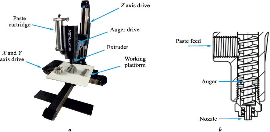
The core principle of the MPD method involves applying a paste comprising metal powder onto the substrate in necessary layers, as dictated by the 3D model, until the product is fully formed [15]. This paste consists of metal particles bonded by a mixture of water and a binder: 90 wt. % metal powder and 10 wt. % liquid. Throughout printing, the liquid evaporates, leaving a “green” part composed of metal particles with less than 1 % binder residue. an illustration of a 3D printer utilizing MPD technology and a diagram of the extruder can be observed in Fig. 1.
Fig. 1. MPD 3D printer (Metallic 3D, a) and extruder diagram (b) |
Currently, there are limited number of manufacturers producing 3D printers using MPD technology, such as Rapidia (Canada), Metallic 3D (US), and Mantle (US). It is worth noting that there are no off-the-shelf solutions available for manufacturing multi-material products using the MPD method [16]. However, devices employing this technology can be adapted for multi-material product fabrication by either swapping raw material cartridges during printing or utilizing multiple nozzles [17].
Numerous studies have investigated the production of multi-material products utilizing MPD technology and similar approaches. In a study by the authors of [18], samples derived from metal pastes composed of steel, copper, and alumina were prepared and analyzed. the investigation into dissimilar metal interactions revealed minimal differences in 3D shrinkage and increased porosity within the transition zone. Notably, the transition zone between steel and copper exhibited alloy mixing, resulting in a fourfold increase in electrical conductivity and a 34 % rise in Young’s modulus compared to a pure steel sample. However, the multi-material system of steel with alumina displayed a 17 % lower Young’s modulus compared to the pure steel sample, without any alloy mixing. In another study documented by the authors of [19], multi-material samples of the copper-chemically modified graphene system, produced via the MPD method, were examined. These samples were designed to simulate an electric battery. the resultant metal and graphene pastes demonstrated the potential for producing prototype electric batteries, suggesting that additive technologies could effectively fabricate electrodes and electric batteries with customized configurations.
From the aforementioned literature review, it is evident that the metal paste deposition method for manufacturing multi-materials presents several advantages over other types of additive technologies. Although there have been studies conducted on multi-material production using this method, they remain relatively limited. Therefore, a promising area of focus involves expanding the research scope to further investigate multi-materials produced via the MPD method. For example, high-entropy alloys (HEAs) like CoCrFeMnNi exhibit superior impact strength, particularly in cryogenic conditions, and have a higher endurance limit compared to 304L and 316L steels. Furthermore, they demonstrate enhanced structural stability under ion irradiation compared to nickel alloys and possess commendable corrosion resistance, comparable to steel 304L. However, replacing traditional engineering alloys such as stainless steels or nickel-based superalloys with CoCrFeMnNi might escalate product costs. In this context, the concept of creating multi-materials within the CoCrFeMnNi–316L system could offer a promising solution to enhance performance characteristics without significantly inflating production expenses [20]. the addition of W to CoCrFeMnNi can elevate its melting point. HEAs like CrMoNbWV exhibit heightened corrosion strength, hardness, and wear resistance. This alloy type holds promise for applications in friction pairs and conditions involving severe abrasive wear within aggressive environments [21].
The objective of this study was to investigate samples of the multi-material systems comprising 316L steel with CoCrFeMnNiW0.25 and 316L steel with CrMoNbWV obtained from metal paste. to achieve this goal, several key issues needed addressing: to analyze the impact of metal powder morphology and particle size distribution, along with the transitional layer comprising mixed powders, on the formation process of multi-material samples, and to examine the porosity, microstructure, phase composition, and hardness of the metal paste derived from 316L steel subsequent to sintering.
Materials and methods
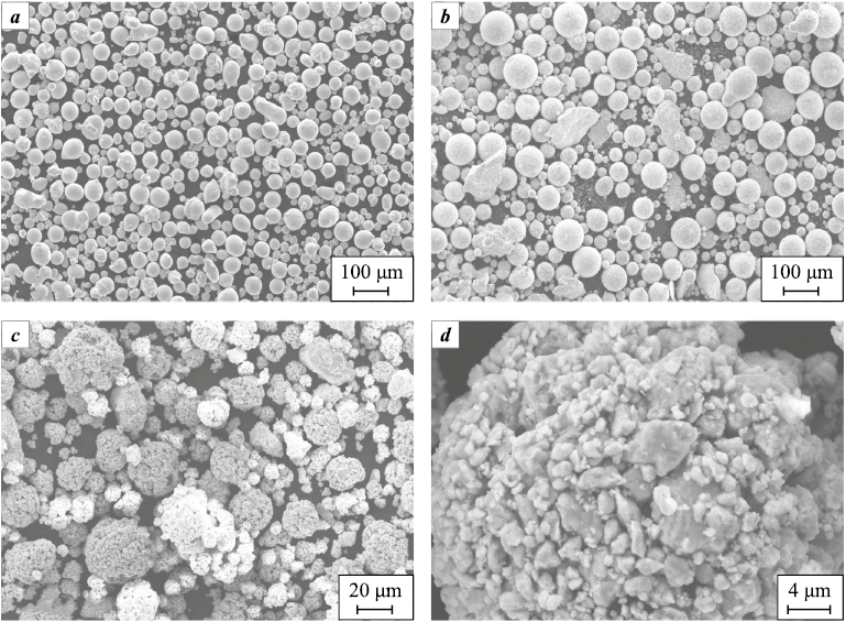
To produce multi-material samples of the 316L–CoCrFeMnNiW0.25 and 316L–CrMoNbWV systems, we used specific metal powders depicted in Fig. 2. Examination of the powders revealed that 316L steel and CoCrFeMnNiW0.25 HEA powders consist predominantly of spherical particles exhibiting a smooth surface texture, with occasional irregularly shaped particles present. The 316L steel powder was manufactured through gas atomization by Sphere M LLC (Metlino Village, Chelyabinsk Region). the CoCrFeMnNiW0.25 HEA powder was produced via mechanical alloying in a Fritsch Pulverisette 4 planetary mill (Fritsch GmbH, Germany) as follows: duration 5–20 h, main disk rotation speed 200–400 rpm, bowl rotation speed 400–800 rpm (rotation against the disk), grinding media of 10 mm steel balls with a ball-to-powder weight ratio of 20:1. Following mechanical alloying, the particles underwent spheroidization using a Tekna TEK-15 unit (Tekna, Canada) employing inductively coupled plasma with an Ar–H2 gas mixture. the powder feed rate ranged from 20 to 25 g/min [22]. Similarly, the CrMoNbWV HEA powder was obtained through mechanical alloying using a Fritsch Pulverisette 4 planetary mill (Fritsch GmbH, Germany) as follows: duration 5 h, main disk/bowl rotation speed 350/700 rpm, grinding balls of high-strength steel with a diameter of 7–10 mm, maintaining a material-to-ball weight ratio 1:20 [21]. After mechanical alloying, the particles underwent agglomeration in a spray drying unit.
Fig. 2. Morphology of metal powders: |
The particle size distribution of the powders was determined using laser diffraction analysis conducted with an Analysette 22 NanoTec Plus particle size analyze (Fritsch GmbH, Germany). the results of these measurements are detailed in Table 1.
Table 1. Particle size distribution of metal powders
| ||||||||||||||||||||||
Table 1 showcases distinct particle size distributions among the powders. These variations can potentially lead to uneven shrinkage during the fabrication of multi-material products. Additionally, it’s important to note that the data acquired for the CrMoNbWV HEA pertain to the particles constituting the powder granules, as they disintegrated during analysis due to dissolution in water.
For the metal paste comprising 316L steel, CoCrFeMnNiW0.25 HEA, and CrMoNbWV HEA, a 7 % polyvinyl alcohol solution in water served as the binder. This solution was prepared through continuous stirring at 80 °C until the polyvinyl alcohol crystals completely dissolved in water (~2 h).
The 316L steel metal paste was prepared for printing using a Tronxy Moore 1 Mini Clay 3D printer (Tronxy, China). While this printer typically employs ceramic paste extrusion technology, it was adapted to accommodate metal paste by adjusting the specific consistency required.
Sintering of the 316L steel paste was conducted in a vacuum furnace from Carbolite Gero GmbH & Co. KG, Germany. the sintering process followed these modes: heating to 600 °C at a rate of 5 °C/min, holding for 1 h; subsequent heating to 1380 °C at a rate of 5 °C/min, holding for 3 h, and cooling within the oven. the treatment occurred within a hydrogen atmosphere. the etching process to reveal the microstructure of 316L steel sample was performed using aqua regia.
For examining the macrostructure of the transition zone in the “green” bodies of the multi-material samples, a Leica M125 stereomicroscope (Leica Microsystems, Germany) was employed.
The melting point of the CoCrFeMnNiW0.25 HEA powder was determined via differential scanning calorimetry (DSC) using a NETZSCH DSC 404 F3 Pegasus unit (NETZSCH GmbH, Germany) This analysis was conducted in a corundum crucible within a high-purity argon environment, employing a heating rate of 20 K/min in the temperature range of 1200 to 1600 °C. the DSC curve depicting the melting process exhibits an endothermic peak in the heat flow versus temperature relationship, delineating three distinct characteristic points: Tonset , Tpeak and Tend . The peak onset point (Tonset ) is identified as the intersection between the interpolated baseline and the tangent drawn to the deflection point of the ascending side of the peak. the peak point (Tpeak ) signifies the temperature corresponding to the maximum deviation between the DSC curve and the baseline. Finally, the peak end point (Tend ) is recognized as the intersection between the interpolated baseline and the tangent drawn to the deflection point on the descending side of the peak.
The analysis of the microstructure in a 316L steel sample and the examination of the structure of the “green” bodies in multi-material samples were carried out using a Leica DMi8 M optical microscope (Leica Microsystems, Germany). the phase composition was determined through analysis performed with a Rigaku SmartLab X-ray diffractometer (Rigaku Corporation, Japan). Additionally, Vickers microhardness measurements were conducted using a MicroMet 5101 microhardness tester manufactured (Buehler Ltd, USA).
Results and discussion
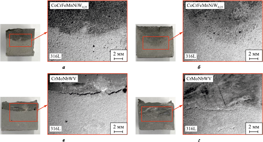
Fig. 3 depicts multi-material samples (“green” bodies) from 316L–CoCrFeMnNiW0.25 and 316L–CrMoNbWV systems after molding. the observations are as follows: the 316L–CoCrFeMnNiW0.25 sample lacking a transition zone of mixed powders displays a predominantly smooth interface with a minor blending of the two alloys (Fig. 3, a); the 316L–CoCrFeMnNiW0.25 sample with a transition zone of mixed powders exhibits an uneven arc-shaped interface, characterized by substantial mixing of the two alloys (Fig. 3, b); the 316L–CrMoNbWV sample without a transition zone of mixed powders showcases a deep crack along the interface, stemming from uneven shrinkage due to varying particle size distributions of the two alloys (Fig. 3, c); the 316L–CrMoNbWV sample featuring a transition zone of mixed powders displays no deep cracks, presenting a smooth interface with a blending of the two alloys (Fig. 3, d).
Fig. 3. Study of transition zones in multi-material samples (“green” bodies) |
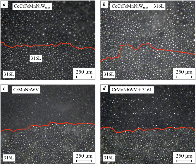
Fig. 4 displays metallographic sections of multi-material samples, referred to as “green” bodies, obtained from the 316L–CoCrFeMnNiW0.25 and 316L–CrMoNbWV systems.
Fig. 4. Analysis of interfaces in multi-material samples (“green” bodies) |
Upon analyzing the metallographic sections, several observations regarding the interfaces in the multi-material samples of the 316L–CoCrFeMnNiW0.25 and 316L–CrMoNbWV systems were noted: the interface between 316L and CoCrFeMnNiW0.25 in the 316L–CoCrFeMnNiW0.25 system displays a smooth transition without any breaks, discontinuities, or defects (Fig. 4, a). Similarly, the interface between 316L and a combination of CoCrFeMnNiW0.25 and 316L exhibits no breaks, discontinuities, or defects, although it appears less distinct compared to the 316L and CoCrFeMnNiW0.25 interface (Fig. 4, b). the interface between 316L and CrMoNbWV is clearly defined, attributed to the considerably smaller size of CrMoNbWV particles in contrast to those of the 316L alloy. This interface also lacks any breaks, discontinuities, or defects (Fig. 4, c). Likewise, the interface between 316L and a combination of CrMoNbWV and 316L presents a less distinct boundary but remains devoid of breaks, discontinuities, or defects (Fig. 4, d). the absence of breaks, discontinuities, and other defects at the interfaces within the multi-material samples from the 316L–CoCrFeMnNiW0.25 and 316L–CrMoNbWV systems suggests a decreased likelihood of defect formation post the sintering process.
Based on the analysis of literature data concerning the manufacturing of multi-material products using AT, it has been highlighted that the transition zone, where dissimilar alloys are blended, necessitates specifically optimized printing parameters [23–25]. This is crucial because the properties of the alloy mixture differ from those of pure alloys, and utilizing printing parameters designed for pure alloys with the mixture can lead to an unstable synthesis process, potentially resulting in defects. In the MPD method, the primary interaction between dissimilar alloys occurs during the sintering phase. Given the limitation in separately influencing the zone of alloy differences during sintering, it becomes preferable to minimize the mixing zone between alloys to reduce the volume of material susceptible to unstable synthesis. From the observations in Figs. 3 and 4, it can be inferred that the absence of a transition zone between mixed 316L steel and CoCrFeMnNiW0.25 powders is desirable due to significant mixing between two alloys occurs. For the 316L–CrMoNbWV system, having a transition zone of mixed powders is preferable. This choice aims to mitigate the impact of uneven shrinkage, thereby minimizing the occurrence of potential defects.
The sintering process for multi-material samples following the molding phase requires knowledge of the alloy’s melting point to select appropriate sintering parameters. While sintering modes for 316L steel have been previously established, the melting point of CoCrFeMnNiW0.25 HEA powder was determined via differential scanning calorimetry, as detailed in Table 2.
Table 2. Investigation of CoCrFeMnNiW0.25 powder melting temperature
| ||||||||||||||||||||||||||||||||||||||
Table 2 indicates that the average melting point of CoCrFeMnNiW0.25 ranges from 1373 ± 19 to 1403 ± 16 °C, while the melting point of 316L steel falls between 1402 ± 15 to 1435 ± 30 °C [26]. Consequently, the sintering parameters utilized for 316L steel may not be suitable for sintering multi-material samples within the 316L–CoCrFeMnNiW0.25 system. Therefore, adjustments are necessary, suggesting a reduction in temperature by approximately 30–45 °C compared to the sintering modes established for 316L steel. Additionally, Table 2 highlights a trend of increasing temperature during measurement. This temperature rise might be attributed to the burnout of manganese, which possesses the lowest melting and boiling points among all elements present in the HEA. Any alteration in the concentration of this less refractory element could contribute to an increase in temperature. Consequently, when determining sintering parameters, it is advisable to prioritize initial melting point measurements of CoCrFeMnNiW0.25 and conducting further experimental studies.
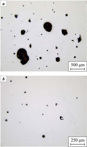
Fig. 5 displays the outcomes of sintering a metal paste composed of 316L steel, revealing the presence of large (Fig. 5, a) and small (Fig. 5, b) spherical pores in the sintered 316L steel sample. It is plausible that these pores were formed due to the existence of gas bubbles generated during the preparation of the paste. to mitigate the occurrence of such defects, an additional step involving degassing can be implemented in the metal paste production process. Moreover, to address porosity concerns, another effective technique involves hot isostatic pressing (HIP) subsequent to sintering.
Fig. 5. Porosity of a 316L sintered specimen |
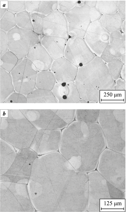
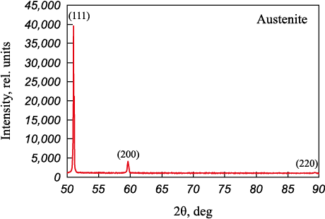
Fig. 6 depicts the microstructure of a sintered 316L steel sample, showcasing the presence of coarse austenite grains that are characteristic of austenitic stainless 316L steel [27]. This observation aligns with the results obtained from X-ray diffraction analysis (Fig. 7). the Axalit Metal software (Axalit SOFT LLC, Yekaterinburg) was used to determine an average grain area of 0.05 mm2, derived from three Field-of-Views (FOVs) with approximately 25 grains in each. It’s worth noting that the grain size in the sintered 316L steel metal paste sample is notably larger compared to samples produced by binder jetting or fused deposition methods [28; 29]. This disparity in grain size might be attributed to the larger particle size of the powder used to create the metal paste of 316L steel, consequently leading to larger original grains in the sintered product [30]. the microhardness values recorded were 132 ± 4 HV, indicating a lower hardness compared to samples sintered after binder jetting or fused deposition [31].
Fig. 6. Microstructure of metal 316L paste after sintering
Fig. 7. X-ray diffraction patterns of metal 316L paste after sintering |
Conclusions
This study involved samples from the multi-material systems of 316L-CoCrFeMnNiW0.25 and 316L–CrMoNbWV, which were prepared using a metal paste. Our investigation focused on understanding the impact of metal powder morphology, particle size distribution, and the presence of a transition layer composed of mixed powders on the development of multi-material samples. Additionally, we examined the porosity, microstructure, phase composition, and hardness of sintered 316L steel fabricated from the metal paste. the conclusions drawn from the results of this study are as follows:
1. For the molding of multi-material samples of the 316L–CoCrFeMnNiW0.25 system, the creation of a transition zone comprising mixed 316L steel and CoCrFeMnNiW0.25 powders is unnecessary due to the strong mixing observed between the two alloys. Conversely, in the 316L–CrMoNbWV system, forming a transition zone of mixed powders is essential to mitigate the impact of uneven shrinkage.
2. The sintering parameters for multi-material samples of the 316L–CoCrFeMnNiW0.25 system need to be altered compared to those used for pure alloys. Specifically, it is recommended to reduce the sintering temperature by 30–45 °C relative to the sintering temperature employed for 316L steel.
3. The sintered 316L steel sample revealed the presence of large and small spherical pores, a microstructure characterized by sizable austenite grains (with an average grain area of approximately 0.05 mm2), and a microhardness reading of 132 ± 4 HV.
References
1. Akshaya S.L., Prakash A., Bharati Raj J. Applications of functionally graded materials in structural engineering – A review. Lecture Notes in Civil Engineering. 2021;97:553–566. https://doi.org/10.1007/978-3-030-55115-5_51
2. Ghanavati R., Naffakh-Moosavy H. Additive manufacturing of functionally graded metallic materials: A review of experimental and numerical studies. Journal of Materials Research and Technology. 2021;13:1628–1664. https://doi.org/10.1016/j.jmrt.2021.05.022
3. Bandyopadhyay A., Zhang Y., Onuike B. Additive manufacturing of bimetallic structures. SN Applied Sciences. 2020;17(2):256–294. https://doi.org/10.1007/s42452-020-2918-6
4. Bandyopadhyay A., Traxel K.D., Lang M., Juhasz M., Eliaz N., Bose S. Alloy design via additive manufacturing: Advantages, challenges, applications and perspectives. Materials Today. 2022;52:207–224. https://doi.org/10.1016/j.mattod.2021.11.026
5. El-Galy I.M., Saleh B.I., Ahmed M.H. Functionally graded materials classifications and development trends from industrial point of view. SN Applied Sciences. 2019;1:1378. https://doi.org/10.1007/s42452-019-1413-4
6. Saleh B., Jiang J., Fathi R., Al-hababi T., Xu Q., Wang L., Song D., Ma A. 30 Years of functionally graded materials: An overview of manufacturing methods, applications and future challenges. Composites. Part B: Engineering. 2020;201:108376. https://doi.org/10.1016/j.compositesb.2020.108376
7. Liu G., Zhang X., Chen X., He Y., Cheng L., Huo M., Yin J., Hao F., Chen S., Wang P., Yi S., Wan L., Mao Z., Chen Z., Wang X., Cao Z., Lu J. Additive manufacturing of structural materials. Materials Science and Engineering: R: Reports. 2021 1;145:100596. https://doi.org/10.1016/j.mser.2020.100596
8. Zhai X., Jin L., Jiang J. A survey of additive manufacturing reviews. Materials Science in Additive Manufacturing. 2022;1(4):21. https://doi.org/10.18063/msam.v1i4.21
9. Srivastava M., Rathee S., Patel V., Kumar A., Koppad P.G. A review of various materials for additive manufacturing: Recent trends and processing issues. Journal of Materials Research and Technology. 2022;21:2612–2641. https://doi.org/10.1016/j.jmrt.2022.10.015
10. Zhang X., Liang E. Metal additive manufacturing in aircraft: Current application, opportunities and challenges. IOP Conference Series: Materials Science and Engineering. 2019;493(1):012032. https://doi.org/10.1088/1757-899X/493/1/012032
11. Gunasekaran J., Sevvel P., Solomon I.J. Metallic materials fabrication by selective laser melting: A review. Materials Today Proceedings. 2021;37(2):252–256. https://doi.org/10.1016/j.matpr.2020.05.162
12. Nandhakumar R., Venkatesan K. A process parameters review on selective laser melting-based additive manufacturing of single and multi-material: Microstructure, physical properties, tribological, and surface roughness. Materials Today Communications. 2023;35:105538. https://doi.org/10.1016/j.mtcomm.2023.105538
13. Camargo I.L., Fortulan C.A., Colorado H.A. A review on the ceramic additive manufacturing technologies and availability of equipment and materials. Cerâmica. 2022;68:329–347. https://doi.org/10.1590/0366-69132022683873331
14. Saadi M., Maguire A., Pottackal N.T., Thakur M., Ikram M., Hart A.J., Ajayan P., Rahman M. Direct Ink Writing: A 3D printing technology for diverse materials. Advanced Materials. 2022;34(28): 2108855. https://doi.org/10.1002/adma.202108855
15. Agrawal R., Anantachaisilp F., Tirano J., Zea Ramirez H., Marquez Z., Luhrs C. Paste-based 3D printing of metallic materials: effect of binders and precursor sizes. Materials Research Express. 2019;6(10):106561. https://doi.org/10.1088/2053-1591/ab3996
16. Rocha V.G., Saiz E., Tirichenko I.S., García-Tuñón E. Direct ink writing advances in multi-material structures for a sustainable future. Journal of Materials Chemistry A. 2020;8(31):15646–15657. https://doi.org/10.1039/D0TA04181E
17. Liu W., Zhang Y.S., Heinrich M.A., Ferrari F., Jang H.L., Bakht S.M., Alvarez M.M., Yang J., Li Y.-C., Santiago G. Trujillo-de, Miri A.K., Zhu K., Khoshakhlagh P., Prakash G., Cheng H., Guan X., Zhong Z., Ju J., Zhu G.H., Jin X., Shin S.R., Dokmeci M.R., Khademhosseini A. Rapid continuous multimaterial extrusion bioprinting. Advanced Materials. 2017;29(3):1604630. https://doi.org/10.1002/adma.201604630
18. Xu C., Quinn B., Lebel L.L., Therriault D., L’espérance G. Multi-material Direct Ink Writing (DIW) for complex 3D metallic structures with removable supports. ACS Applied Materials & Interfaces. 2019;11(8):8499–8506. https://doi.org/10.1021/acsami.8b19986
19. Rocha V.G., García-Tuñón E., Botas C., Markoulidis F., Feilden E., D’Elia E., Ni N., Shaffer M., Eduardo Saiz E. Multimaterial 3D printing of graphene-based electrodes for electrochemical energy storage using thermoresponsive inks. ACS Applied Materials & Interfaces. 2017;9(42):37136–37145. https://doi.org/10.1021/acsami.7b10285
20. Sokkalingam R., Chao Z., Sivaprasad K., Muthupandi V., Jayaraj J., Ramasamy P., Eckert J., Prashanth K.G. Additive manufacturing of CoCrFeMnNi high-entropy alloy/AISI 316L stainless steel bimetallic structures. Advanced Engineering Materials. 2022;25(7):2200341. https://doi.org/10.1002/adem.202200341
21. Razumov N., Makhmutov T., Kim A., Shemyakinsky B., Shakhmatov A., Popovich V., Popovich A. Refractory CrMoNbWV high-entropy alloy manufactured by mechanical alloying and spark plasma sintering: Evolution of microstructure and properties. Materials. 2021;14(3):621. https://doi.org/10.3390/ma14030621
22. Makhmutov T., Razumov N., Kim A., Ozerskoy N., Mazeeva A., Popovich A. Synthesis of CoCrFeNiMnW0.25 high-entropy alloy powders by mechanical alloying and plasma spheroidization processes for additive manufacturing. Metals and Materials International. 2021;27(1):50–54. https://doi.org/10.1007/s12540-020-00747-0
23. Wits W.W., Amsterdam E. Graded structures by multi-material mixing in laser powder bed fusion. CIRP Annals. 2021;70(1):159–162. https://doi.org/10.1016/j.cirp.2021.03.005
24. Chen K., Wang C., Hong Q., Wen S., Zhou Y., Yan C., Shi Y. Selective laser melting 316L/CuSn10 multi-materials: Processing optimization, interfacial characterization and mechanical property. Journal of Materials Processing Technology. 2020;283:116701. https://doi.org/10.1016/j.jmatprotec.2020.116701
25. Wei C., Li L. Recent progress and scientific challenges in multi-material additive manufacturing via laser-based powder bed fusion. Virtual and Physical Prototyping. 2021;16(3):347–371.
26. Pichler P., Simonds B.J., Sowards J.W., Pottlacher G. Measurements of thermophysical properties of solid and liquid NIST SRM 316L stainless steel. Journal of Materials Science. 2020;55(9):4081–4093. https://doi.org/10.1007/s10853-019-04261-6
27. Santamaria R., Salasi M., Bakhtiari S., Leadbeater G., Iannuzzi M., Quadir M.Z. Microstructure and mechanical behaviour of 316L stainless steel produced using sinter-based extrusion additive manufacturing. Journal of Materials Science. 2022;57(21):9646–9662. https://doi.org/10.1007/s10853-021-06828-8
28. Cabo Rios A., Hryha E., Olevsky E., Harlin P. Sintering anisotropy of binder jetted 316L stainless steel: part II – microstructure evolution during sintering. Powder Metallurgy. 2022;65(4):283–295. https://doi.org/10.1080/00325899.2021.2020486
29. Sadaf M., Bragaglia M., Nanni F. A simple route for additive manufacturing of 316L stainless steel via Fused Filament Fabrication. Journal of Manufacturing Processes. 2021;67:141–150. https://doi.org/10.1016/j.jmapro.2021.04.055
30. Park D.Y., Lee S.W., Park S.J., Kwon Y-S., Otsuka I. Effects of particle sizes on sintering behavior of 316L stainless steel powder. Metallurgical and Materials Transactions A. 2013;44: 1508–1518. https://doi.org/10.1007/s11661-012-1477-x
31. Krakhmalev P., Fredriksson G., Svensson K., Yadroitsev I., Yadroitsava I., Thuvander M., Thuvander M., Peng R. Microstructure, solidification texture, and thermal stability of 316L stainless steel manufactured by laser powder bed fusion. Metals. 2018;8(8):643. https://doi.org/10.3390/met8080643
About the Authors
D. V. MasayloRussian Federation
Dmitry V. Masaylo – Cand. Sci. (Eng.), Deputy Head of the Laboratory “Synthesis of new materials and structures”
29 Polytekhnicheskaya Str., St. Petersburg 195251, Russian Federation
A. V. Repnin
Russian Federation
Arseniy V. Repnin – Engineer of the Laboratory “Synthesis of new materials and structures”
29 Polytekhnicheskaya Str., St. Petersburg 195251, Russian Federation
A. A. Popovich
Russian Federation
Anatoly A. Popovich – Dr. Sci. (Eng.), Professor, Director of the Institute of Machinery, Materials, and Transport
29 Polytekhnicheskaya Str., St. Petersburg 195251, Russian Federation
N. G. Razumov
Russian Federation
Nikolai G. Razumov – Cand. Sci. (Eng.), Head of the Laboratory “Synthesis of new materials and structures”
29 Polytekhnicheskaya Str., St. Petersburg 195251, Russian Federation
A. K. Mazeeva
Russian Federation
Alina K. Mazeeva – Cand. Sci. (Eng.), Leading Researcher of the Laboratory “Synthesis of new materials and structures”
29 Polytekhnicheskaya Str., St. Petersburg 195251, Russian Federation
Review
For citations:
Masaylo D.V., Repnin A.V., Popovich A.A., Razumov N.G., Mazeeva A.K. Additive technology for forming multi-material samples of “stainless steel – high-entropy alloys” system. Powder Metallurgy аnd Functional Coatings (Izvestiya Vuzov. Poroshkovaya Metallurgiya i Funktsional'nye Pokrytiya). 2024;18(1):62-72. https://doi.org/10.17073/1997-308X-2024-1-62-72


