Scroll to:
Characteristics of granule solidification in gas atomization of molten beryllium
https://doi.org/10.17073/1997-308X-2023-4-16-24
Abstract
Experimental and analytical studies on gas atomization of the molten beryllium and the production of beryllium granules are presented. The impact of various factors, including the choice of gas (nitrogen or helium), the cooling gas flow rate (ranging from 300 to 650 m/s), melt temperature, and droplet size (<500 µm), on the cooling rate and granule properties, is demonstrated. It has been determined that the solidification of beryllium granules can occur through two distinct mechanisms depending on the atomization process. These mechanisms include crystallization and amorphization (glass transition). When beryllium melt is atomized with nitrogen, granules with diameters less than 100 µm solidify via the amorphization mechanism (glass transition), while those with diameters exceeding 300 µm solidify through crystallization. In such cases, a portion of granules with sizes ranging from 100 to 300 µm undergoes a mixed mechanism solidification. In this process, the surface becomes amorphous, while the central part crystallizes, resulting in the formation of a “shell” on the surface, marking the transition from the glass transition mechanism to the crystallization mechanism. The thickness of this “shell” depends on the granule diameter, measuring 10–15 µm for 300 µm granules and 20–25 µm for 100 µm granules. The findings from this research align well with the hypothesis of a glass-crystalline mechanism of beryllium granule solidification, which leads to their separation at the interfacial boundary. Such solidification through a mixed mechanism results in the creation of a removable “crust” on the granule, which is typically more contaminated with impurities. Understanding this effect opens up possibilities for practical applications in the production of specialized materials from beryllium. The ability to separate the “crust” from the “core” provides the conditions for obtaining specialized sintered beryllium grades suitable for use in nuclear reactors and foil production, where a beryllium microstructure with “clean” boundaries is essential.
Keywords
For citations:
Syrnev B.V., Pestova G.S., Semilutskaya O.V., Tuganbaev F.S. Characteristics of granule solidification in gas atomization of molten beryllium. Powder Metallurgy аnd Functional Coatings (Izvestiya Vuzov. Poroshkovaya Metallurgiya i Funktsional'nye Pokrytiya). 2023;17(4):16-24. https://doi.org/10.17073/1997-308X-2023-4-16-24
Introduction
The beryllium industry employs various methods to produce beryllium powders, with mechanical methods being the most widely used for reducing the particle size of technical beryllium ingots, electro-refined beryllium flakes, and distilled beryllium granules to less than 56 μm. However, it's important to note that mechanical grinding during this process generates heat and leads to surface oxidation of the powders. The surface oxidation results in the presence of beryllium oxide on the powder particles, and this oxide material is subsequently incorporated into the grain boundaries of the compacted beryllium. It serves as a dispersion-strengthening phase [1–6]. This particular phase plays a significant role in influencing the processes of structure formation and the development of both strength and plastic properties in sintered beryllium.
In [7–9], novel insights into the mechanism of degradation of an oxide film covering beryllium particles during the hot consolidation of powders were substantiated. It has been demonstrated that the initially amorphous beryllium oxide film undergoes crystallization at temperatures exceeding 700 °C. The crystallization mechanism, whether homogeneous or heterogeneous, depends on the presence of fusible impurities. This, in turn, dictates the nanostructure of the resulting discrete oxide particles and, consequently, influences the strengthening effect observed in sintered beryllium. These established quantitative patterns contribute to the scientific foundation for controlling the mechanical properties of sintered beryllium. This is especially crucial in ensuring the quality of “instrumental” beryllium grades [10–16].
Nonetheless, there are other significant applications of beryllium where the presence of beryllium oxide and other impurities on grain boundaries, and correspondingly on the particle surface of initial powders, is undesirable. These applications pertain to beryllium grades used in nuclear reactors, specifically as neutron reflectors, and in foil production. In the former case, impurities at the grain boundaries can adversely affect the relaxation of thermal stresses that occur during reactor operation, potentially leading to the development of cracks in critical components. In the latter case, the presence of oxide at the grain boundaries reduces the impermeability (vacuum density) of thin foils, which is unacceptable when employed in X-ray technology.
There is existing literature on the utilization of distilled coarse-grained beryllium for reactor-grade applications [3; 6; 17], and fine-grained beryllium produced through hydride technology for foil-grade purposes [18]. Nevertheless, the application of these technologies has limitations.
In the 1970s, significant advancements were made in beryllium granule metallurgy. Specialized equipment was developed for the atomization of molten beryllium, including rotary atomizers (VIAM, Russia), centrifugal atomizers (Leybold–Heareus, Germany), and gas atomizers “Sphere” (KhPTI, Ukraine). However, experimental studies revealed that despite decreased contamination, the granule surface still retained impurities due to interaction with the gas atmosphere.
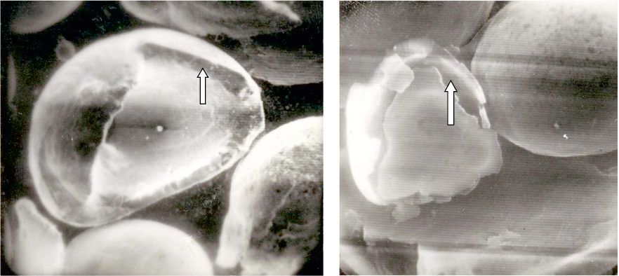
In practical applications of gas atomization for spraying beryllium melt, it was observed that certain-sized granules developed a “shell” upon solidification. This “shell” comprised beryllium enriched with oxygen, nitrogen, and iron (Fig. 1).
Fig. 1. Microimages of granules captured by a scanning electron microscope (×200) |
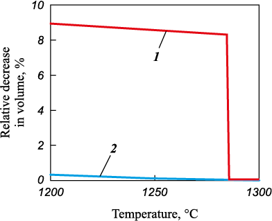
Understanding the underlying causes and mechanisms responsible for the formation of the “shell” is crucial for its utilization in quality control of both granules and densely sintered beryllium materials. It was essential to investigate the hypothesis that the formation and subsequent detachment of the “shell” result from a significant alteration in volumetric contraction during the granule’s solidification process. This transformation occurs due to the shift from the glass transition mechanism to the crystallization mechanism, accompanied by a reduction in the cooling rate as the solidification front progresses from the granule’s surface to its core. During the crystallization of the melt, the granule’s density increases from 1.69 to 1.85 g/cm3, leading to an 8.6 % reduction in the granule’s volume 8.6 % [2]. In contrast, when solidification takes place through the glass transition (amorphization) mechanism, the reduction in the granule’s volume is significantly less (Fig. 2).
Fig. 2. Hypothetical curve of volumetric shrinkage |
Published information regarding the feasibility of obtaining beryllium metallic glasses is limited. However, it is noteworthy that the glass transition of granules composed of pure metals can be facilitated when the metal is saturated with gases [19; 20]. This saturation can be achieved through gas atomization techniques, specifically employing gases such as nitrogen in the atomization of beryllium, at both subsonic (300 m/s) and supersonic (650 m/s) velocities. The research aimed to investigate the dynamic changes in cooling rates experienced by beryllium granules as the solidification front progresses from the granule’s surface towards its center. The primary objective was to determine the conditions necessary for implementing a combined “glass-crystalline” solidification mechanism for these granules.
The objective of this study was to investigate the gas jet spraying method for beryllium melt with the aim of identifying technological procedures for the production of granules. These granules would possess a structure that, during subsequent processing, facilitates the efficient removal of impurities from their surfaces.
Experimental
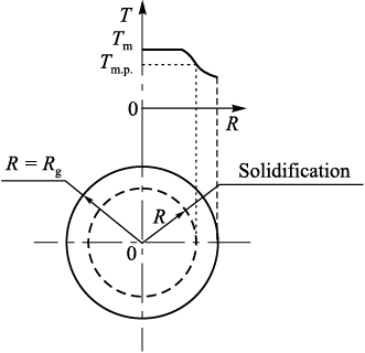
Numerical studies into the solidification of beryllium melt droplets were conducted using two approaches: a graphical-analytical method employing universal dimensionless graphs [21], and an analytical method involving the solution of differential equations governing heat conduction [22]. In the first approach, the study addressed the problem of non-steady-state heat conduction during the incremental solidification of a cooled sphere due to uniform convective heat dissipation from its surface (Fig. 3).
Fig. 3. Schematic representation of granule solidification |
The calculations did not account for variations in droplet volume during cooling, nor did they consider the influence of the already solidified droplet layer on the cooling process. The temperature of the gaseous medium was assumed to be 40 °C. At the initial time (τ = 0), all points within the droplet with a radius Rg possessed the same melt temperature Тm = 1350 °С.
Under these specified conditions, the temperature at any point within the droplet becomes solely a function of time and radius. Numerical investigations were conducted for beryllium droplets with diameters ranging from 50 to 400 μm while being subjected to cooling by nitrogen, helium, and air at both subsonic (300 m/s) and supersonic (650 m/s) velocities.
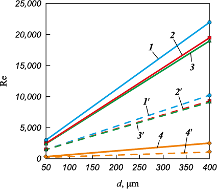
The heat exchange mode between the droplet (or granule) and the coolant flow is determined by the Reynolds criterion (Re) (Fig. 4):
\[{\mathop{\rm Re}\nolimits} = \frac{{{V_{\rm{g}}}d}}{{{\nu _{\rm{g}}}}},\]
where Vg represents the gas flow velocity, d stands for the droplet diameter, νg denotes the kinematic viscosity of the flowing medium.
Fig. 4. Reynolds criterion for gas flow as a function |
In the context of heat exchange involving a spherical body and a gas flow, the Nusselt criterion (Nu) governs both laminar and turbulent regimes:
\[{\rm{Nu}} = 2 + 0.69{{\mathop{\rm Re}\nolimits} ^{0.5}}{\Pr ^{0,33}} = \frac{{\alpha d}}{{{\lambda _{\rm{g}}}}},\]
where Pr signifies the Prandtl criterion, equal to 0.67 for monatomic gases and 0.72 for diatomic gases; α represents the coefficient of heat transfer, W/(m2·K); λg denotes the thermal conductivity coefficient of the energy-carrying gas, W/(m·K).
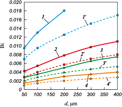
The Biot number (Bi) quantifies the relationship between the rate of heat transfer and the rate of heat conduction within the granule (Fig. 5):
\[{\rm{Bi}} = \frac{{\alpha d}}{{{\lambda _T}}},\]
where λT represents the thermal conductivity of the melt, W/(m·K).
Fig. 5. Biot number for gas flow as a function |
The total heat released by the granule prior to solidification is determined as follows:
qb = cm (Tm – Tm.p.),
where сm signifies the specific heat capacity, Тm denotes the melt temperature, Тm.p. represents the melting point of beryllium (1285 °С).
Time and cooling rates for different cooling conditions were determined using dimensionless graphs [14], which represent numerical solutions of the following set of equations:
\[\begin{array}{c}Y\frac{{\partial {\theta ^*}}}{{\partial {\tau ^*}}} = \frac{{{\partial ^2}{\theta ^*}}}{{\partial {r^{*2}}}} + 2\frac{{\partial {\theta ^*}}}{{{r^*}\partial {r^*}}}{\rm{at}}({\rm{ }}{R^*} < {r^*} < 1),\\ - \frac{{\partial {\theta ^*}}}{{\partial {r^*}}} = \frac{{{\theta ^*}}}{\beta }{\rm{at}}({\rm{ }}{r^*} = 1),\\\frac{{d{R^*}}}{{d{\tau ^*}}} = \frac{{\partial {\theta ^*}}}{{\partial {r^*}}}{\rm{at}}({\rm{ }}{r^*} = {R^*}),\end{array}\]
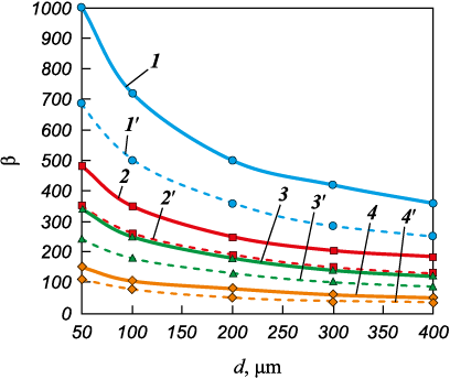
where \(Y = \frac{{{c_T}\left( {{T_{{\rm{m.p.}}}} - \theta } \right)}}{{{q_{{\rm{b}}}}}}\) is the relative heat content of solid phase; сТ is the specific heat content of granule; θ is the granule temperature; \({\theta ^*} = \frac{{\theta - 1}}{{{T_{{\rm{m.p.}}}} - t}}\) is the dimensionless temperature; t is the gas temperature; \({\tau ^*} = \frac{{\tau {\lambda _T}\left( {{T_{{\rm{m.p.}}}} - t} \right)}}{{R_{\rm{g}}^2{\rho _T}{q_{{\rm{b}}}}}}\) is the dimensionless time; \({r^*} = \frac{r}{{R_{\rm{g}}^{}}},{\rm{ }}{R^*} = \frac{R}{{R_{\rm{g}}^{}}}\) are the relative radii, representing the current radius and solidification front; β = 1/Bi is the coefficient (Fig. 6); r is the “current” radius varying from 0 to Rg .
Fig. 6. β = 1/Bi as a function of granule diameter, gas type, and gas flow rate |
The calculation of cooling time was conducted as follows:
\[\tau = \frac{{{\tau ^*}{\rho _T}{q_{{\rm{b}}}}R_{\rm{g}}^2}}{{{\lambda _T}\left( {{T_{\rm{m}}} - {T_{\rm{g}}}} \right)}},\]
where τ\(^*\) is the relative time determined through the graphs [14]; ρТ is the melt density; Rg is the granule radius; Тg is the temperature of the dispersing gas.
The calculation of cooling rate was performed as follows:
\[{V_{{\rm{cool}}}} = \frac{{{T_{\rm{m}}} - {T_{{\rm{m.p.}}}}}}{\tau }.\]
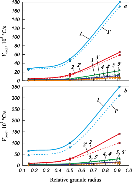
The outcomes of the numerical research employing the graphical analytical method are depicted in Fig. 7.
Fig. 7. Cooling rate of granules in nitrogen (а) and helium (b), |
In order to assess the accuracy of data obtained through the first method, numerical investigations were carried out using the second method. This involved solving the following differential equation:
\[\frac{{\partial \theta }}{{\partial \tau }} = \alpha \left( {\frac{{{\partial ^2}\theta }}{{\partial {r^2}}} + \frac{{2\partial \theta }}{{r\partial r}}} \right).\]
The boundary conditions were set as follows:
\({\left( {\frac{{\partial \theta }}{{\partial r}}} \right)_{r\,\, = \,\,{R_{\rm{g}}}}} = - {\left( {\frac{\alpha }{\lambda }\theta } \right)_{r\,\, = \,\,{R_{\rm{g}}}}}\) – on the droplet surface;
\({\left( {\frac{{\partial \theta }}{{\partial r}}} \right)_{r\,\, = \,\,0}} = 0\) – in the droplet center.
The initial conditions (at τ = 0): θ = Тm – Тm.p. for 0 < r < Rg .
The solution to the differential equation was obtained in [5] in the form:
\[\theta = \frac{{{{\rm T}_{\rm{m}}} - {T_{{\rm{m.p.}}}}}}{{{T_{\rm{m}}} - {T_{\rm{g}}}}} = 1 - \sum\limits_{n = 1}^\infty {{B_n}\exp \left( { - \mu _n^2{F_0}} \right)} ,\]
where n = 1, 2, 3…; F0 is the Fourier number; Вn are the coefficients determined by:
\[{B_n} = \frac{{6{\rm{B}}{{\rm{i}}^2}}}{{\mu _n^2(\mu _n^2 + {\rm{B}}{{\rm{i}}^2} - {\rm{Bi}})}};\]
μn – are the roots of the characteristic equation:
\[{\rm{tg}}\mu = - \frac{\mu }{{{\rm{Bi}} - 1}}.\]
The solidification time of melt droplet \(\tau = \frac{{{F_0}{c_{\rm{m}}}{\rho _T}{r^2}}}{{{\lambda _T}}},\) where r = (1 – R\(^*\))R.
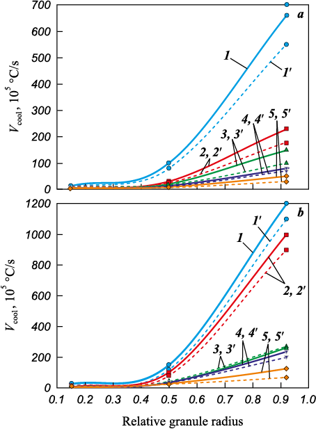
The computed results for the rates of solidification of beryllium droplets using the analytical method are presented in Fig. 8.
Fig. 8. Cooling rate of granules in nitrogen (а) and helium (b), |
Result and discussion
An analysis of the dependencies obtained through the two methods reveals that as the granule diameter increases from 50 to 400 μm, the solidification rate near the droplet’s surface decreases from values on the order of 107 to 105 °С/s. Additionally, an increase in the thermal conductivity of the gas results in a 2–3 times increase in this rate (Figs. 7 and 8). It is worth noting that data regarding the cooling rates of droplets by nitrogen and helium, as determined by these two different methods, exhibit reasonably good agreement, despite some quantitative differences.
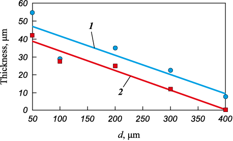
Experiments involving the atomization of beryllium granules with nitrogen have revealed that granules measuring 300 µm in size possess a removable “shell” of approximately 10 µm thickness (R\(^*\) = 0.92). Expanding on the previously mentioned hypothesis, plotting this experimental data on the graph (refer to Fig. 7, a) facilitates the determination of the cooling rate at which beryllium solidification through the glass transition mechanism takes place. This rate is approximately 106 °С/s when nitrogen exits the nozzle at velocities ranging from 300 to 650 m/s. These determined rates closely resemble those associated with the glass transition of certain metals [12; 13]. Further scrutiny of the graphical data (as observed in Fig. 7, a) permits the creation of a curve depicting the thickness of the “shell” enveloping the granules as a function of granule size and the flow rate of the dispersing energy-carrying gas (Fig. 9).
Fig. 9. The thickness of the surface shell in relation |
The acquired experimental and analytical results align well with the hypothesis of a “glass-crystalline” mechanism governing the solidification of beryllium granules, which results in their stratification along the interphase boundary. When beryllium melt is atomized with nitrogen, granules smaller than 100 µm solidify through the glass transition mechanism (amorphized), while those with diameters exceeding 300 µm solidify via the crystallization mechanism. Granules ranging in size from 100 to 300 μm undergo a mixed solidification mechanism, leading to the peeling of the “shell” on the surface during the transition from the glass transition mechanism to the crystallization mechanism. The thickness of this “shell” varies based on the granule diameter, measuring 10–15 μm (d = 300 μm) and 20–25 μm (d = 100 μm). During the cooling process of the fine fraction <100 µm and the “shell,” the amorphous structure undergoes a transformation into a crystalline one. Understanding this studied effect may hold practical significance.
It is worth noting that the surface of beryllium granules, including the “shell,” becomes enriched with nitrogen and oxygen during nitrogen atomization. This enrichment results in an increased impurity content at the boundaries of compacted beryllium derived from these granules. The presence of impurities at grain boundaries negatively affects several vital physical and mechanical properties, such as high-temperature plasticity, stress relaxation capacity, foil vacuum density, and others.
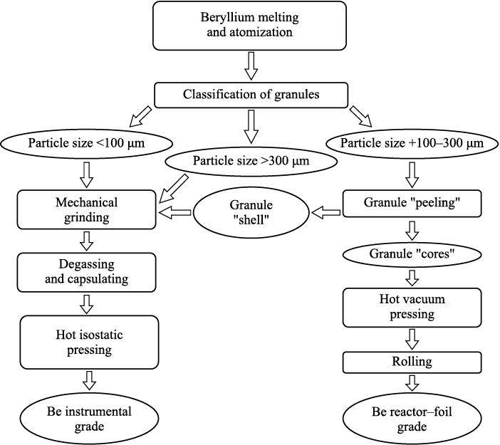
In order to produce a grade of beryllium with reduced impurity content along the grain boundaries and enhanced physical and mechanical properties, it is essential, during the classification phase, to separate a fraction of spherical powders with a “shell” ranging from +100 to 300 μm in size. Subsequently, this “shell” should be removed (peeled) without grinding, using established methods such as a shock-centrifugal mill under specific operating conditions. The resulting granules can then be utilized for the subsequent consolidation into workpieces intended for the production of reactor reflectors–moderators and rolling of foils.
Summarizing the outcomes from our prior works [7–9] and considering the distinct requirements for various beryllium grades (demanding high precision elastic limits for instrument grade, lower relaxation resistance, and vacuum tightness for reactor and foil grades), we propose a technological flowchart for the production of sintered beryllium varieties tailored for diverse applications (Fig. 10). After the melt atomization, the granules are categorized into three fractions: those below 100 µm (amorphous), those exceeding 300 µm (crystalline), and those ranging from +100 to 300 µm (with a shell). Subsequently, the +100–300 µm fraction is subjected to a “peeling” process, resulting in the production of foil reactor grade material through hot pressing. The remaining fractions (–100 µm, +300 µm and “shell”), post-peeling, are directed toward the manufacturing of an instrument-grade product, which contains a higher concentration of beryllium oxide, serving as a reinforcing hardening phase.
Fig. 10. Flowchart of production process for different structural grades of sintered beryllium |
Conclusions
1. The formation mechanism of the surface shell on granules during gas atomization of beryllium melt, resulting from the “amorphous-crystalline” solidification of the melt droplets, has been substantiated.
2. The thickness of the surface shell has been determined as a function of the dispersing gas supply rate and granule size.
3. A technological layout for granule processing at the production of beryllium for various applications has been proposed.
References
1. Webster D. The effect of low melting phases on the elevated temperature microstructural stability of hot pressed beryllium. Metallurgical and Materials Transactions A. 1975;6(4):803–808.
2. Papirov I.I., Tikhinskii G.F. Physical metal science of beryllium. Moscow: Atomizdat, 1968. 451р. (In Russ.).
3. Davydov D.A., Kholopova O.V., Kolbasov B.N. Inflammation and oxidation characteristics of beryllium: ITER final report. TA. No. ITA-81-06 Be Dust Explosion, July 2005.
4. Davydov D.A., Kholopova O.V., Kolbasov B.N. Formation and degradation of oxide films on beryllium. Voprosy atomnoi nauki i tekhniki. Ser.: Termoyadernyi sintez. 2010;(2):39–48. (In Russ.).
5. Nikolaenko A.A., Tuzov Yu.V. The effect of grain boundary oxide inclusions on the mechanical properties of hot-pressed beryllium. Voprosy atomnoi nauki i tekhniki. Ser. Termoyadernyi sintez. 2012;(2):52—59. (In Russ.).
6. Taylor N., Baker D., Cattaglia S. Key issues in the safety and licensing of ITER. In: IAEA, 3rd TM ‘’First generation of fusion power plants: Design and technology’’ (Vienna, Austria, 13–15 July 2009); 9th TM “Fusion power plant safety’’ (Vienna, Austria, 15–17 July 2009). CD-ROM proc., Thursday-2009-07-16.
7. Revutskiy A.V., Syrnev B.V., Lopatin V.Yu., Semilutskaya O.V., Segeda T.A. Study of reinforcing phase formation at the grain boundaries of sintered beryllium. Russian Journal of Non-Ferrous Metals. 2021;62(1):125–131. https://doi.org/10.3103/S1067821221010132
8. Revutskiy A.V., Syrnev B.V., Semilutskaya O.V. Study on hardening potential of isostatic pressed beryllium. Key Engineering Materials. 2020;842:199–204. https://doi.org/10.4028/www.scientific.net/KEM.842.199
9. Revutsky A.V., Syrnev B.V., Semilutskaya O.V. Study of beryllium hardening obtained by powder metallurgy. Vestnik Karagandinskogo Universiteta. Ser. Fizika. 2021;2(102):40–49. https://doi.org/10.31489/2021Ph2/40-49
10. Webster D., Crooks D.D. Creep mechanisms in beryllium. Metallurgical and Materials Transactions. 1976;(7A): 1307–1315.
11. Crawford R.F., Burns A.B. Strength efficiency and design data for beryllium structures ASD. Technical Report 61.692 US AIR Force. Ohio. 1962.
12. Cai Y., Wu S., Xu R., Yu J. Pressure-induced phase transition and its atomistic mechanism in BeO: A theoretical calculation. Physical Review. Letters. 2006;73(18):184104. https://doi.org/10.1103/PhysRevB.73.184104
13. Sebahaddin A., Murat D. Pressure-induced phase transition of BeO. Solid State Communications. 2009; 149(9-10):345–348.
14. Weisz M., Mollen J., Voron J. Possibility of the appearance of a liquid phase at 430 °C in commercial beryllium. Journal of Nuclear Materials. 1963;(10):56–59.
15. Turner G.I., Lane R.A. The effect of powder particle size on the mechanical properties of hot pressed P1 beryllium. In: Beryllium: Proc. Conf. (London, October, 1977). P. 1–15.
16. Webster D., Crooks D.D., Vidoz A.E. The effect of oxide dispersion on the recrystallization of beryllium. Metallurgical and Materials Transactions. 1974;4(12):2841–2847.
17. Tuzov Yu.V., Gorokhov V.A., Pakhomov Ya.D., Pronin V.N. Beryllium – material of nuclear and thermonuclear technology. Voprosy atomnoi nauki i tekhniki. Ser. Termoyadernyi sintez. 2009;(2):124–127. (In Russ.).
18. Markushkin Yu.E., Gorlevskiy V.V., Zabrodin A.V., Tuzov Yu.V. Beryllium for X-ray technology – new possibilities of nanocrystalline material. Voprosy atomnoi nauki i tekhniki. Ser. Materialovedenie i novye materialy. 2012;(1):130–136. (In Russ.).
19. Silaev A.F., Fishman V.D. Dispersion of liquid metals and alloys. Moscow: Khimiya, 1983. 144 р. (In Russ.).
20. Metal Glass. Eds. J.J. Gidman, H.J. Limi. Moscow: Metallurgiya, 1984. 264 р. (In Russ.).
21. Kazakova E.A. Granulation and cooling of nitrogen-containing fertilizers. Moscow: Khimiya, 1980. 289 р. (In Russ.).
22. Lykov A.V. Theory of thermal conductivity. Moscow: Vysshaya shkola, 1967. 600 р. (In Russ.).
About the Authors
B. V. SyrnevKazakhstan
Boris V. Syrnev – Dr. Sci. (Eng.), Leading Researcher of the Scientific Center “Veritas”
19 D. Serikbaev Str., Ust-Kamenogorsk 070004, Kazakhstan
G. S. Pestova
Kazakhstan
Galina S. Pestova – Cand. Sci. (Eng.), Leading Design Engineer of the Scientific Center “Veritas”
19 D. Serikbaev Str., Ust-Kamenogorsk 070004, Kazakhstan
O. V. Semilutskaya
Kazakhstan
Oksana V. Semilutskaya – Senior Lecturer of the School “Metallurgy and mineral processing”
19 D. Serikbaev Str., Ust-Kamenogorsk 070004, Kazakhstan
F. S. Tuganbaev
Kazakhstan
Farit S. Tuganbaev – Leading Process Engineer of the Scientific Center “Veritas”
19 D. Serikbaev Str., Ust-Kamenogorsk 070004, Kazakhstan
Review
For citations:
Syrnev B.V., Pestova G.S., Semilutskaya O.V., Tuganbaev F.S. Characteristics of granule solidification in gas atomization of molten beryllium. Powder Metallurgy аnd Functional Coatings (Izvestiya Vuzov. Poroshkovaya Metallurgiya i Funktsional'nye Pokrytiya). 2023;17(4):16-24. https://doi.org/10.17073/1997-308X-2023-4-16-24


