Scroll to:
In situ study of mechanical properties and structural transformations during heating of WC–TaC–Co cemented carbides in a transmission electron microscope column
https://doi.org/10.17073/1997-308X-2023-4-41-50
Abstract
This study investigated the hardness of lamella with varying thickness, obtained from a massive, fine-grained cemented carbide comprising WC–6 %Co–0.2 %TaC, characterized by an average grain size of approximately 5 μm. The picoindentation method was employed for this analysis. Picoindentation was carried out using a Berkovich diamond indenter with a radius of curvature around 50 nm, and the experimental data were analyzed using the Oliver–Pharr model. The results revealed a significant correlation between hardness and lamella thickness. The hardness of the electron transparent section (thickness less than 100 nm) of the lamella measured 11.3±2.8 GPa, while the electron nontransparent section (thickness more than 200 nm) exhibited a hardness of 20.8±1.2 GPa. The lower hardness in electron transparent objects (thickness ~100 nm) is likely attributed to a combination of factors, including the potential bending of thin cobalt layers, the presence of edge effect, and closely spaced structural defect dislocations on the lamella surface. In situ TEM studies were conducted to examine structural transformations during the heating of WC–6 %Co–0.2 %TaC lamella, including in the presence of oxide phases (WOx ). Oxide phases on the lamella’s surface were generated by oxidizing the lamella at 200 °C in an air atmosphere. The results indicated that heating up to 500 °C did not bring about significant changes in the structure. However, at 600 °C, there was a notable thinning of cobalt layers due to intense surface diffusion of cobalt. Simultaneously, the formation of nanosized particles of the Co3W3C phase, ranging in size from 5 to 20 nm, was observed in the binder. These particles resulted from a shift in the equilibrium phase composition of the carbide, changing from a two phase region (WC + γ) to a three phase region (WC + γ + Co3W3C) as a consequence of the lamella’s oxidation.
Keywords
For citations:
Zaitsev A.A., Loginov P.A., Levashov E.A. In situ study of mechanical properties and structural transformations during heating of WC–TaC–Co cemented carbides in a transmission electron microscope column. Powder Metallurgy аnd Functional Coatings (Izvestiya Vuzov. Poroshkovaya Metallurgiya i Funktsional'nye Pokrytiya). 2023;17(4):41-50. https://doi.org/10.17073/1997-308X-2023-4-41-50
Introduction
Cemented carbides, often referred to as hardmetals, represent a class of metal composites characterized by a hard carbide skeleton embedded within a ductile metallic binder predominantly composed on iron-group metals. Due to their exeptional performance characteristics, carbide tools are widely used in the metalworking and mining industries, as well as in construction and mechanical engineering.
In the metalworking and mining sectors, the most significant cost savings are often achieved by increasing metal cutting speeds and rock drilling. This results in higher tool loads and elevated temperatures, which can reach 1000 °C or more on the tool surface. High contact stresses can lead to substantial plastic deformation of carbide cutting edges, and it is often this plastic deformation that determines the tool’s lifespan. Research into the plastic deformation of hardmetals at elevated temperatures [1] has revealed that the carbide skeleton is destroyed during high-temperature deformation. This, in turn, results in the formation of cohesive phase interlayers between WC grains, facilitating the of grain-boundary sliding process.
In recent years, efforts have been made to enhance the plastic deformation resistance of hardmetals through the addition of refractory metal carbides [2–5]. Various works have employed Mo2C [6–11], TiC, and TaC [12–19] additives. It has been found that even small additions of TaC significantly improve the plastic deformation resistance of cemented carbides at higher temperatures. It is hypothesized that tantalum affects the interfacial energy at the WC/Co and WC/WC interfaces, resulting in the reinforcement of the carbide skeleton [18]. Nevertheless, the mechanism of tantalum carbide’s influence on the mechanical and high-temperature properties of hardmetals remains inadequately studied, as indicated by the data in [20].
Over the last few decades, new approaches to studying mechanical properties and structural characteristics of materials have been intensively developed. These approaches include micromechanical testing [21; 22], as well as the investigation of structural transformations during the heating of electron-transparent objects directly within the transmission electron microscope (TEM) column [23–25]. Such studies yield substantial fundamental insights, enabling a deeper comprehension of the deformation and fracture mechanisms of bulk materials, as well as the prediction of their performance characteristics.
The objective of this study was to examine the mechanical properties at room temperature and structural transformations at elevated temperatures of hardmetals containing TaC additives. The investigations were conducted in situ within a transmission electron microscope column at both ambient and higher temperatures.
Experimental
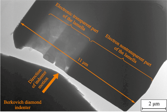
The subject of investigation in this study was a fine-grained WC–6 %Co–0.2 %TaC hard metal, which was derived from a mixture of WC, Co, and TaC powders. A lamella was cut out from a solid carbide sample using the focused ion beam method on the FEI Quanta 200 3D (FEI Company, USA) for the picoindentation experiment and then soldered to a special holder, as depicted in Figure 1.
Fig. 1. Appearance of the lamella before picoindentation tests |
Picoindentation [26] was carried out in situ within a PEM column using a “Hysitron PI 95 TEM Picoindenter” holder (Bruker, USA) designed for mechanical testing and equipped with a Berkovich diamond indenter. The indentation process was recorded in situ in a JEM-2100 TEM column (JEOL Ltd., Japan). The lamella had a length of about 11 μm and consisted of two sections with varying thickness: one of them was electron-transparent (with a thickness ranging from 70 to 120 nm), while the other was nontransparent to the electron beam (with a thickness exceeding 200 nm).
According to the well-known Oliver–Pharr model [27], which is applicable for interpreting picoindentation results, hardness is determined by the following equation:
| H = Fmax/A, | (1) |
where Fmax represents the maximum load, N; A is the surface area of the indenter’s contact with the sample, m2.
The contact area, accounting for the radius of curvature of a real Berkovich indenter (approximately 50 nm), was determined as follows:
| \[A = 24.5h_c^2 + 1.65 \cdot {10^{ - 6}}{h_c}.\] | (2) |
The depth of contact between the indenter and the sample (hc , m) was calculated using the equation:
| \[{h_c} = {h_{\max }} - 0.75{F_{\max }}{\left( {\frac{{dh}}{{dF}}} \right)_{{F_{\max }}}},\] | (3) |
where hmax is the maximum depth of indenter penetration, m.
The lamella was heated using a “Gatan heating holder 652” (Gatan, USA) by passing an electric current through a ring-shaped tantalum heater that surrounded the lamella. The heating rate was set at 50±5 K/min. In order to examine the alloy’s structure, temperatures of 300, 400, 500 and 600 °C were selected. In situ imaging of the structure was performed within a JEM-2100 TEM column (JEOL Ltd., Japan) at these specific temperatures. The samples were allowed to stabilize for several minutes to eliminate temperature gradients, which could cause sample drift. The recording duration ranged from 15 to 20 min before activating the heating process.
Results and discussion
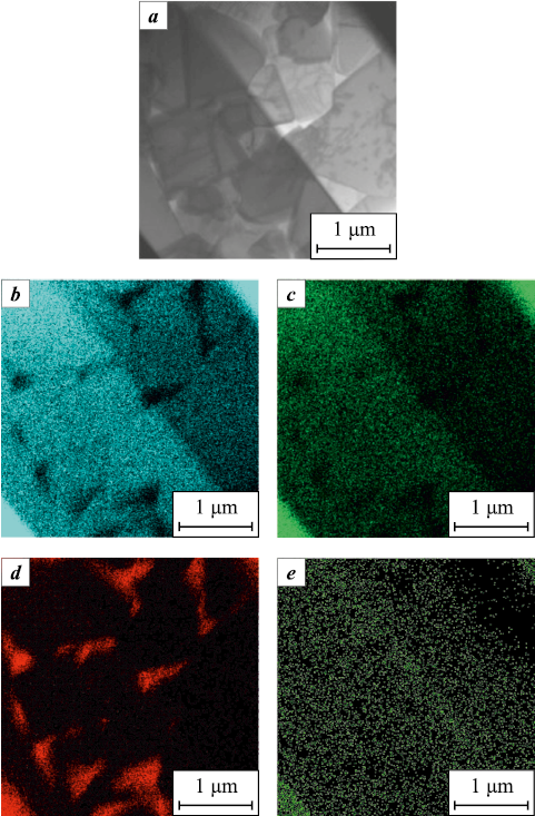
The average grain size of the examined hard metal, composed of WC–6 %Co–0.2 %TaC, measured approximately 0.5 μm (Fig. 2). The thickness of the cobalt interlayers fell within the range of 100 to 200 nm. As a result, the size relationship between the indenter and the structural elements of the alloy leads us to conclude that during picoindentation, multiple grains of the carbide phase and cobalt interlayers were concurrently deformed. The resultant picohardness characterizes the hardness of the entire composite, rather than individual structural components.
Fig. 2. EDS maps of electron-transparent part |
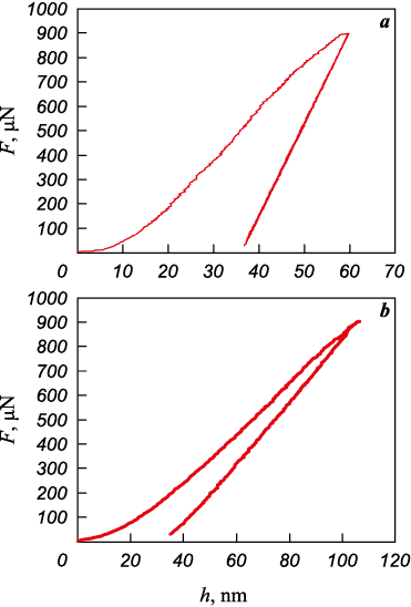
Figure 3 displays two characteristic curves obtained during picoindentation of a hard metal. A series of 12 individual tests were conducted in different areas of the lamella, with a maximum test load of 900 µN, and the exposure time at maximum load was 5 s. The resulting curves can be categorized based on the maximum indenter penetration depth (hmax). The first group comprises tests with a penetration depth ranging from 100 to 115 nm, while the second group covers tests with a depth of 50 to 60 nm. Notably, all tests in the first group were executed on a thin (electron-transparent) section of the lamella, whereas those in the second group were performed on a thicker section. Figure 3 illlustrates that at the maximum load, there is a slight displacement (drift) of the testing system, ranging from 1 nm (Fig. 3, a) to 2 nm (Fig. 3, b). This corresponds from 2 to 4 % of the maximum indenter penetration depth. Consequently, the displacement of the testing system has minimal impact on the shape of the displacement-load curve. The drift rate fluctuates between 0.2 to 0.4 nm/s at a load of 900 μN. However, since the relationship between drift speed and load is unknown, no adjustments were made to the experimental data.
Fig. 3. Typical indentation curves |
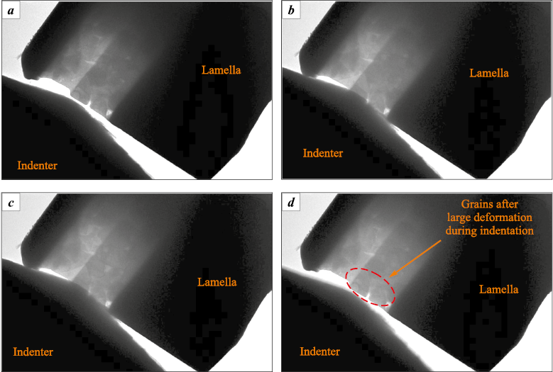
Figure 4 presents a videogram depicting the indentation of a thin section of the lamella. Clearly, during the test, the indenter made contact with multiple WC grains and the cobalt layers that separate them. Importantly, no cracks or defects were observed after the indentation of the electron-transparent portion of the lamella (Fig. 4, d).
Fig. 4. Videogram of the picoindentation of electron-transparent section of the lamella |
The picoindentation results were analyzed using the Oliver–Pharr model [22], and the calculated hardness values are summarized in Table.
Picoindentation curve results analized using the Oliver–Pharr model
|
The hardness of the electron-transparent section of the lamella measured 11.3±2.8 GPa, while the electron non-transparent section records a hardness of 20.8±1.2 GPa. Indentation of the electron-transparent part of the lamella is associated with significantly greater deformations, resulting in an underestimation of hardness and greater result dispersion. This reduction in hardness is likely attributed to edge effects and the proximity of structural defects, which are often located on the surface of the sample. The proximity of structural defects also accounts for the higher plasticity observed in nanoscale objects during in situ micromechanical tests. Another possible factor that could distort the picoindentation results is the bending of cobalt layers. It’s probable that during picoindentation, there is a transition from purely compressive to mixed bending-compressive loads.
The hardness obtained from the electron nontransparent region correlates well with published data, which suggests that for massive samples of fine-grained WC–6 %Co alloys, hardness typically falls within the range of 18 to 20 GPa [28].
As previously mentioned, during the operation of hardmetals in cutting metals and mining minerals, local temperature increases of up to 1000 °C or more are observed. This rise in the temperature of the air-exposed surface layers of the tool results in the formation of oxides due to interaction with atmospheric oxygen, contributing to abrasive (or hydro-abrasive) corrosion-abrasive wear. Therefore, the study of structural transformations of carbide surface layers during heating in an oxidizing atmosphere is crucial for understanding the dynamic processes occurring in hardmetals tool during operations.
In order to investigate the characteristics of structural transformations in lamellas when heated within a transmission electron microscope column in the presence of oxide phases, a lamella was created from a fine-grained hard metal WC–6 %Co–0.2 %TaC. The TEM column is maintained under deep vacuum (less than 10\(^–\)5 Pa), making it impossible to create even a very rarefied oxidizing atmosphere. As a result, the lamella was subjected to oxidation at a temperature of 200 °C for 4 h in an air atmosphere. These mild oxidation conditions led to the development of an oxidized layer on the lamella’s surface, which was intended to serve as a source of oxygen with further temperature increases.
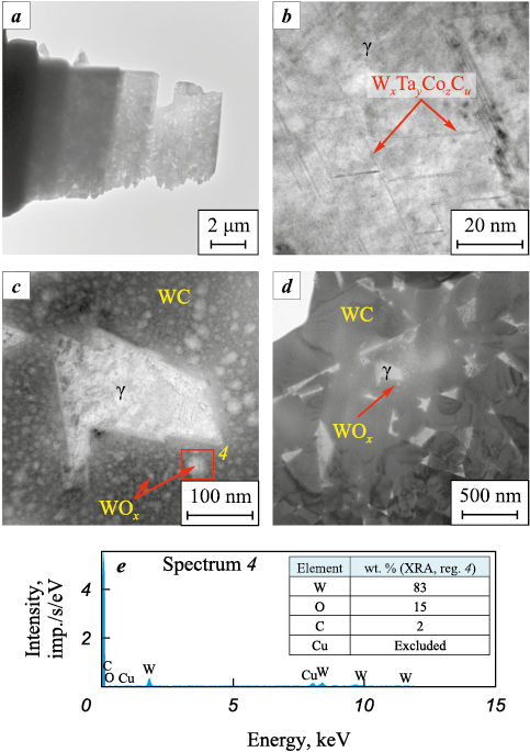
TEM images of the lamella structure after oxidation are depicted in Figure 5. The sample exhibited a typical hard metal structure with faceted WC grains ranging in size from 0.2 to 0.6 μm, embedded within a γ phase binder (cobalt-based solid solution), with interlayer thicknesses spanning from 50 to 250 nm. As seen in Figure 5, b, the binding γ phase contains needle-shaped particles measuring about 5 nm in diameter, the composition of which can presumably be described by the formula: WxTayCozCu . The surface of WC grains is uniformly covered with nanoparticles ranging in size from 5 to 30 nm, which, according to electron probe microanalysis (EPMA), are tungsten oxides WOx with variable stoichiometry.
Fig. 5. TEM images of the fine-grained WC–6 %Co–0.2 %TaC lamella after oxidation |
It’s worth noting that the presence of copper, as indicated by EPMA data (Fig. 5, e), is an artifact attributed to the soldering of the lamella to the copper holder. No oxide particles were detected in the cobalt phase, which confirms the greater affinity of tungsten for oxygen compared to cobalt.
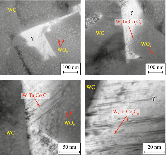
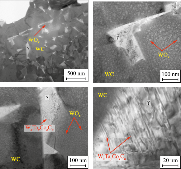
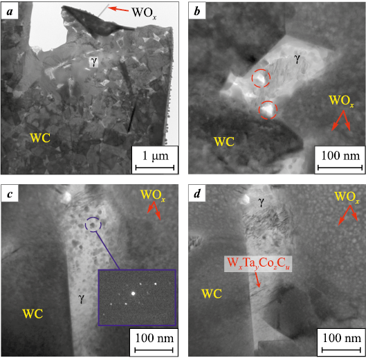
In order to investigate the behavior of the oxidized hard metal after heating, the lamella was subjected to temperature increases within the TEM column, reaching 400, 500 and 600 °C. The images illustrating the alloy’s structure after heating phase are presented in Figures 6, 7 and 8, respectively.
Fig. 6. TEM images of the WC–6 %Co–0.2 %TaC lamella after heating to 400 °C
Fig. 7. TEM images of the WC–6 %Co–0.2 %TaC lamella after heating to 500 °С
Fig. 8. TEM images of the WC–6 %Co–0.2 %TaC lamella after heating to 600 °С |
Up to a temperature of 500 °C, no significant alterations in the lamella’s structure are observed. Some thinning of the cobalt layers was detected, which enhances the contrast of the WxTayCozCuphase. At a temperature of 600 °C, rapid thinning of the cobalt interlayers commences, leading to the formation of voids (Fig. 8, b). The redistribution of cobalt across the sample’s surface, including the surface of tungsten carbide grains, appears to occur through a mechanism of surface diffusion. This effect was previously established when heating a lamella composed of a hard metal that has not undergone oxidation [29]. In the case of grains coated with WOx nanoparticles, no droplet accumulations of the cobalt phase are formed, which is explained by the limited wettability of oxide particles by cobalt.
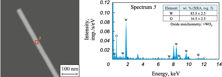
Another phenomenon observed in the γ phase at a temperature of 600 °C is the development of equiaxed nanoparticles with sizes ranging from 5 to 20 nm, as clearly depicted in Figure 8, d. Based on the results of microdiffraction analysis (see the inset in Figure 8, c), the following interplanar distances were identified within this phase, measured in nm: 0.239, 0.205 and 0.1846. These correspond to reflections from crystallographic planes with indices (422), (440) and (620) of Co3W3C phase, with reference interplanar distances of 0.2269, 0.1965, and 0.1758 nm, respectively. The noticeable discrepancy between the experimental and reference interplanar distances can be attributed to the temperature-induced expansion of the crystal lattice. Without accounting for the anisotropy of the linear expansion coefficient of the Co3W3C phase (approximately 9·10\(^–\)6 K\(^–\)1) at 600 °C, the reference lattice periods increase to 0.23212, 0.20172, and 0.18102 nm, aligning more closely with the experimental data. The formation of the Co3W3C phase arises as a consequence of a shift in the carbon balance due to the lamella’s oxidation, leading to an alteration in the equilibrium phase composition of the carbide from a two-phase region WC + γ to a three-phase region WC + γ + Co3W3C. In addition to the surface diffusion of cobalt and the formation of Co3W3C phase, the appearance of WOx particles along the edges of the lamella was observed. Some of these particles took the form of nanofibers with a diameter of roughly 30 nm and a length of approximately 0.8 μm. Electron-probe microanalyzer (EPMA) was employed to determine the composition of these particles, as illustrated in Figure 9, which corresponds to tungsten oxide with stoichiometry closely resembling WO2 .
Fig. 9. EPMA results of oxide particles formed at the edge of the WC–6 %Co–0.2 %TaC lamella |
Conclusions
The study examined the hardness of the lamella with varying thickness, composed of WC–6 %Co–0.2 %TaC alloy, using picoindentation. The results clearly illustrate that the hardness values obtained via picoindentation are notably influenced by the lamella’s thickness. The hardness of the electron-transparent segment of the lamella measures 11.3±2.8 GPa, while the electron-opaque portion records a hardness of 20.8±1.2 GPa. The lower hardness observed in electron transparent regions (thickness ~100 nm) is likely due to a combination of various factors, including potential bending of thin cobalt layers, the presence of edge effects, and the proximity of closely spaced structural defect sites along the lamella’s surface.
In situ studies were conducted to investigate structural transformations during heating of WC–6 %Co–0.2 %TaC alloy, including in the presence of oxide phases. The findings revealed that up to a temperature of 500 °C, no significant structural changes were observed. However, at 600 °C, a rapid thinning of cobalt layers commenced, due to intensive surface diffusion of cobalt. Simultaneously, the formation of nanosized particles of the Co3W3C phase, with sizes ranging from 5 to 20 nm, was documented within the binder. This formation can be attributed to a shift in the equilibrium phase composition of the carbide, shifting it from a two-phase region to a three-phase region as a consequence of the lamella’s oxidation.
References
1. Östberg G., Buss K., Christensen M., Norgren S., Andrén H.-O., Mari D., Wahnström G., Reineck I. Mechanisms of plastic deformation of WC–Co and Ti(C, N)–WC–Co. International Journal of Refractory Metals and Hard Materials. 2006;4(1-2):135–144. https://doi.org/10.1016/j.ijrmhm.2005.04.009
2. Lay S., Hamar-Thibault S., Lackner A. Location of VC in VC, Cr3C2 codoped WC–Co cermets by HREM and EELS. International Journal of Refractory Metals and Hard Materials. 2002;20(1):61–69. https://doi.org/10.1016/S0263-4368(01)00071-3
3. Yamamoto T., Ikuhara Y., Watanabe T., Sakuma T., Taniuchi Y., Okada K., Tanase T. High resolution microscopy study in Cr3C2-doped WC–Co. Journal of Materials Science. 2001;36:3885–3890. https://doi.org/10.1023/A:1017953701641
4. Jaroenwald A., Yamamoto T., Ikuhara Y., Sakuma T., Taniuchi T., Okada K., Tanase T. Segregation of vanadium at the WC/Co interface in VC-doped WC–Co. Journal of Materials Research. 1998;13(9):2450–2452. https://doi.org/10.1557/JMR.1998.0341
5. Roebuck B., Gee M.G. TiC and Ti(C,N) cermet micro-structures. In: Proc. 12th Int. Plansee Seminar. Eds. H. Bildstein, H.M. Ortner. Innsbruck, Tirol, 1989. Vol. 2. P. 1–29.
6. Viatte T., Bolognini S., Cutard T., Feusier G., Mari D., Benoit W. Investigation into the potential of a composite combining toughness and plastic deformation resistance. International Journal of Refractory Metals and Hard Materials. 1999;17(1-3):79–89. https://doi.org/10.1016/S0263-4368(98)00044-4
7. Cutard T., Bolognini S., Feusier G., Verdon C., Viatte T., Benoit W. Microstructure and mechanical properties of Ti(C, N)–Mo2C–(Ni, Co) cermets as a function of their initial chemical composition. Key Engineering Materials. 1997;132–136:747–750. https://doi.org/10.4028/www.scientific.net/KEM. 132-136.747
8. Feusier G., Cutard T., Verdon C., Viatte T., Benoit W. High temperature properties of TiCN–Mo2C–Co cermets studied by mechanical spectroscopy. Journal de Physique IV. 1996;6:C8-751–C8-754. https://doi.org/10.1051/jp4:19968163
9. Bolognini S., Feusier G., Mari D., Viatte T., Benoit W. High temperature mechanical behaviour of Ti(C, N)–Mo–Co cermets. International Journal of Refractory Metals and Hard Materials. 1998;16(4-6):257–268. https://doi.org/10.1016/S0263-4368(98)00033-X
10. Viatte T., Cutard T., Feusier G., Benoit W. High temperature mechanical properties of Ti(C, N)–Mo2C–Ni cermets studied by internal friction measurements. Journal de Physique IV.1996;6:C8-743–C8-746. https://doi.org/10.1051/jp4:19968161
11. Qiu H., Li X., Pan C., Fan J., Qu S. Effect of Mo2C addition on the formation of core-rim structure and mechanical properties of Ti(C, N)–WC–Mo2C–(Ni, Co) cermet. Journal of Materials Research and Technology. 2023;25:750–762. https://doi.org/10.1016/j.jmrt.2023.05.224
12. Östberg G., Buss K., Christensen M. Norgren S., Andrén H.-O., Mari D., Wahnström G., Reineck I. Effect of TaC on plastic deformation of WC–Co and Ti(C, N)–WC–Co. International Journal of Refractory Metals and Hard Materials. 2006;24(1-2):145–154. https://doi.org/10.1016/j.ijrmhm.2005.04.010
13. Mahmoodan M., Aliakbarzadeh H., Gholamipour R. Microstructural and mechanical characterization of high energy ball milled and sintered WC–10 wt.%Co–xTaC nano powders. International Journal of Refractory Metals and Hard Materials. 2009;27:801–805. https://doi.org/10.1016/j.ijrmhm.2009.02.001
14. Zaitsev A.A., Korotitskiy A.V., Levashov E.A., Avdeenko E.N. Compressive creep of coarse-grain WC–Co and WC–TaC–Co hardmetals with uniform microstructure comprising rounded WC grains. Materials Science and Engineering: A. 2020;795:139998. https://doi.org/10.1016/j.msea.2020.139998
15. Buitrago J.D.R., Plazas A.F.G., Quintero L.K.H. Influence of TiC and Cr3C2 additions on the mechanical properties of a (W–Ti–Cr)C–Co sintered hardmetal. Journal of Materials Research and Technology. 2019;8(6):5736–5744. https://doi.org/10.1016/j.jmrt.2019.09.042
16. Exner H.E. Physical and chemical nature of cemented carbides. International Metals Reviews. 1979;24(1):149–173. https://doi.org/10.1179/imtr.1979.24.1.149
17. Rolander U., Weinl G., Zwinkels M. Effect of Ta on structure and mechanical properties of (Ti,Ta,W)(C,N)–Co cermets. International Journal of Refractory Metals and Hard Materials. 2001;19(4-6):325–328. https://doi.org/10.1016/S0263-4368(01)00042-7
18. Upadhyaya G.S. Materials science of cemented carbides – An overview. Materials and Design. 2001;22(6):483–489. https://doi.org/10.1016/S0261-3069(01)00007-3
19. Farag S., Konyashin I., Ries. B. The influence of grain growth inhibitors on the microstructure and properties of submicron, ultrafine and nano-structured hardmetals – A review. International Journal of Refractory Metals and Hard Materials. 2017;77:12–30. https://doi.org/10.1016/j.ijrmhm.2018.07.003
20. Li N., Zhang W., Du Y., Xie W., Wen G., Wang S. A new approach to control the segregation of (Ta, W)C cubic phase in ultrafine WC–10Co–0.5Ta cemented carbides. Scripta Materialia. 2015;100:48–50. https://doi.org/10.1016/j.scriptamat.2014.12.009
21. Nili H., Kalantar-zadeh K., Bhaskaran M., Sriram S. In situ nanoindentation: Probing nanoscale multifunctionality. Progress in Materials Science. 2013;58(1):1–29. https://doi.org/10.1016/j.pmatsci.2012.08.001
22. Taheri M.L., Stach E.A., Arslan I., Crozier P.A., Kabius B.C., LaGrange T., Minor A.M., Takeda S., Tanase M., Wagner J.B., Sharma R. Current status and future directions for in situ transmission electron microscopy. Ultramicroscopy. 2016;170:86-95. https://doi.org/10.1016/j.ultramic.2016.08.007
23. Yoreo J.J.De. In-situ liquid phase TEM observations of nucleation and growth processes. Progress in Crystal Growth and Characterization of Materials. 2016;62(2):69–88. https://doi.org/10.1016/j.pcrysgrow.2016.04.003
24. Song Z., Xie Z.-H. A literature review of in situ transmission electron microscopy technique in corrosion studies. Micron. 2018;112:9–83. https://doi.org/10.1016/j.micron.2018.04.011
25. Chen L.J., Wu W.W. In situ TEM investigation of dynamical changes of nanostructures. Materials Science and Engineering: R: Reports. 2010;70(3-6):303–319. https://doi.org/10.1016/j.mser.2010.06.014
26. Bhushan B., Kulkarni A.V., Bonin W., Wyrobek J.T. Nanoindentation and picoindentation measurements using a capacitive transducer system in atomic force microscopy. Philosophical Magazine A. 1996;74(5): 1117–1128. https://doi.org/10.1080/01418619608239712
27. Oliver W.C., Pharr G.M. An improved technique for determining hardness and elastic modulus using load and displacement sensing indentation experiments. Journal of Materials Research. 1992;7:1564–1583. https://doi.org/10.1557/JMR.1992.1564
28. Konyashin I., Ries B., Lachmann F. Near-nano WC–Co hardmetals: will they substitute conventional coarse-grained mining grades? International Journal of Refractory Metals and Hard Materials. 2010;28(4):489–497. https://doi.org/10.1016/j.ijrmhm.2010.02.001
29. Zaitsev A.A., Konyashin I., Loginov P.A., Levashov E.A., Orekhov A.S. Radiation-enhanced high-temperature cobalt diffusion at grain boundaries of nanostructured hardmetal. Materials Letters. 2021;294:129746. https://doi.org/10.1016/j.matlet.2021.129746
About the Authors
A. A. ZaitsevRussian Federation
Alexander A. Zaitsev – Cand. Sci. (Eng.), Senior Research Scientist of the Laboratory “In situ diagnostics of structural transformations”
4 Bld. 1 Leninskiy Prosp., Moscow 119049, Russia
P. A. Loginov
Russian Federation
Pavel A. Loginov – Cand. Sci. (Eng.), Senior Research Scientist of the Laboratory “In situ diagnostics of structural transformations”
4 Bld. 1 Leninskiy Prosp., Moscow 119049, Russia
E. A. Levashov
Russian Federation
Evgeny A. Levashov – Dr. Sci. (Eng.), Prof., Acad. of the Russian Academy of Natural Science, Head of the Department of Powder Metallurgy and Functional Coatings of NUST MISIS, Head of the Scientific-Educational Centre of SHS of MISIS–ISMAN
4 Bld. 1 Leninskiy Prosp., Moscow 119049, Russia
Review
For citations:
Zaitsev A.A., Loginov P.A., Levashov E.A. In situ study of mechanical properties and structural transformations during heating of WC–TaC–Co cemented carbides in a transmission electron microscope column. Powder Metallurgy аnd Functional Coatings (Izvestiya Vuzov. Poroshkovaya Metallurgiya i Funktsional'nye Pokrytiya). 2023;17(4):41-50. https://doi.org/10.17073/1997-308X-2023-4-41-50


