Scroll to:
Establishing theoretical foundations for predicting the structural and morphological characteristics of diffusion-welded joints of the beryllium–copper composite
https://doi.org/10.17073/1997-308X-2024-2-14-22
Abstract
The paper presents the results of theoretical and experimental studies regarding the quality of diffusion welding of the beryllium–copper composite. Numerical investigations of the parameters of heterodiffusion of diffusants and the thickness of the Be–Cu pair welded joint under varying temperature-time conditions were conducted. The analytical examinations revealed that the thickness of the diffusion weld at the Be–Cu joint varies between 26 and 345 µm, with the temperature increasing from 800 to 1000 °C and the holding time ranging from 20 to 120 min. The calculated layer thickness during the diffusion welding of a Be–Cu pair at 800 °C for 2 h is 65 µm, with 15 µm on the beryllium side and 50 µm on the copper side. Notably, a CuBe3 intermetallic compound zone can form in the diffusion weld, which should be considered an adverse factor that reduces the mechanical properties. To theoretically substantiate the modification of the structure and properties of the diffusion zone, a numerical study of welding was carried out using a 10 μm thick nickel foil spacer, which is readily soluble in beryllium. It was demonstrated that after exposure to temperature-time conditions at 900 °C for 20 min, a 50 µm wide diffusion-bonded joint is formed. Its structure includes two single-phase zones of solid solutions based on copper and beryllium, as well as two two-phase regions consisting of solid solutions hardened with intermetallic compounds. Since the weld lacks structural zones consisting solely of intermetallic compounds (unlike when welding the Be–Cu diffusion pair), there are grounds to anticipate a reduction in the embrittling effect on the weld. The results obtained from the analytical studies can serve as the foundation for a theoretical prediction method for assessing the quality of diffusion welding of the beryllium–copper composite.
Keywords
For citations:
Syrnev B.V., Maslennikov O.I., Semilutskaya O.V. Establishing theoretical foundations for predicting the structural and morphological characteristics of diffusion-welded joints of the beryllium–copper composite. Powder Metallurgy аnd Functional Coatings (Izvestiya Vuzov. Poroshkovaya Metallurgiya i Funktsional'nye Pokrytiya). 2024;18(2):14-22. https://doi.org/10.17073/1997-308X-2024-2-14-22
Introduction
Energy issues have recently become more pressing. The steadily increasing energy consumption has led to a drastic surge in the prices of “carbon” fuels such as gas, oil, and coal. Meanwhile, aspirations for “green” technologies are constrained by limitations in hydro, wind, solar, and geothermal energy. Concurrently, scientists have linked global warming to the use of carbon-based fuels, making the introduction of a “carbon” tax a reasonable measure.
In light of these developments, scientists are redirecting their focus towards new sources of energy, particularly “hydrogen” and “helium”. Overcoming the apprehension surrounding radioactivity, they are also considering the application and further advancement of nuclear energy. One promising avenue in this regard is the development of the fusion energy industry, which offers several key advantages. The process is highly secure, as accidental power excursions in the power reactor are virtually impossible. Fuel reserves in the form of hydrogen isotopes are nearly limitless, and the energy processes are exceptionally eco-friendly compared to traditional thermal and nuclear power plants. International collaborative research groups are actively engaged in this field, notably in the “International Thermonuclear Experimental Reactor” project [1; 2].
The energy generated by thermonuclear reactions between hydrogen isotopes is released in the form of neutron energy (14.1 MeV) and helium ions, specifically alpha particles (3.5 MeV). This energy is absorbed by a specialized device surrounding the plasma called the “blanket” and subsequently removed by the primary coolant. The reactor employs deuterium and lithium as fuel, with tritium being produced during the fusion reaction through contact with lithium [3; 4].
In order to create a fusion reactor, an array of scientific and technical challenges must be addressed. Various components of the reactor are manufactured from materials with exceptional physical and mechanical properties across a wide range of temperatures and loads. These materials must also exhibit erosion and corrosion resistance in diverse environments while remaining unaffected by electromagnetic and electric fields and radioactive radiation, among other factors. Certain grades of steel, heat-resistant alloys, non-ferrous metals like copper, aluminum, beryllium, and tungsten, along with super-hard alloys and ceramic-metal materials, meet these stringent requirements [5–10].
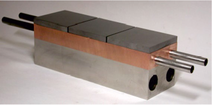
Notably, the inner wall of the toroidal working chamber, a critical component, is constructed using beryllium [11–20]. Physicists involved in the development determined the optimal design for the blanket, a three-layer composite consisting of beryllium, a copper alloy, and stainless steel with an internal channel system for water cooling (Fig. 1). The areas where the constituents of the “beryllium – copper alloy – stainless steel” composite solidify should exhibit high thermal strength and thermal conductivity. Significant progress has been achieved in bonding beryllium and copper through brazing technology [18–20]. Nevertheless, the diffusion welding technique offers certain advantages [21–24] and, according to the authors, holds potential for further enhancing the performance properties of these composites.
Fig. 1. Model of a fragment of the International Thermonuclear Experimental Reactor first wall |
The research aimed to perform numerical studies of the diffusion interaction between composite components and to establish a theoretical framework for predicting the morphology, composition, and structure of diffusion-welded joints.
Experimental
The mathematical tools developed by the staff of the Moscow Engineering Physics Institute under the supervision of Dr. Sci. D. Skorov were used to perform diffusion calculations for the interaction between beryllium and impurities [25]. Principles for shaping the structure of contact zones in heterodiffusion [26] were applyed, and reference data on numerical patterns of diffusion mobility of the elements under investigation [27] were incorporated. Furthermore, corresponding state diagrams [28] were analyzed to formulate an engineering algorithm for both qualitative (structure) and quantitative (width of diffusion and structural zones) assessments of contact zones within a specific beryllium–copper–iron composite.
The experimental and analytical studies were conducted in two distinct stages:
1) analytical studies focused on heterodiffusion parameters (depth and concentration) of elements in the contact zone of diffusion pairs, with a particular emphasis on their variation under different temperature-time conditions;
2) the prediction of the phase composition and sizes of structural zones as a function of diffusion welding modes.
In the analytical study of element heterodiffusion, the concentration of the diffusing element C(z) was calculated as a function of distance (x) from the initial boundary of contact between diffusion pairs and time (τ) using equation [25]
| \[\begin{array}{c}C(z) = C(0)\left\{ {\frac{{\exp \left( { - {z^2}} \right) - \frac{\gamma }{{\sqrt {{\gamma ^2} + 1} }}\exp \left( { - {z^2}\frac{{{\gamma ^2} + 1}}{{{\gamma ^2}}}} \right)}}{{1 - \frac{\gamma }{{\sqrt {{\gamma ^2} + 1} }}}} - } \right.\\\,\left. {\frac{{\sqrt \pi z\left[ {erfC(z) - erfC\,\left( {z\frac{{\sqrt {{\gamma ^2} + 1} }}{\gamma }} \right)} \right]}}{{1 - \frac{\gamma }{{\sqrt {{\gamma ^2} + 1} }}}}} \right\}\,,\end{array}\] | (1) |
where \(z = \frac{x}{2}\sqrt {D\tau } \,,\) \(\gamma = \sqrt {\frac{{{\tau _2}}}{{{\tau _1}}}} \); τ1 and τ2 stand for interaction time at constant and instantaneous diffusion sources, respectively; С(0) represents the concentration of the diffusant element at the contact boundary.
In order to determine the value of С(0), the logic of contact zone formation during the sintering of dissimilar, mutually soluble materials was followed by the researchers [26]. The Be–Cu state diagram revealed that heterodiffusion at the junction of the diffusion pair at a temperature of 800 °C produced an intermediate γ-phase CuBe with a variable composition. This phase contained 11.3 wt. % of Be on the copper side and 86.7 wt. % of Cu on the beryllium side. The specified phase, along with its corresponding chemical composition, was considered as a constant source with concentration values С(0) of the respective diffusant at the interphase under the studied temperature conditions.
The temperature-dependent variation of the diffusion coefficient is represented by the conventional equation [27]
\[D = {D_0}\exp \left( { - \frac{Q}{{RT}}} \right)\,,\]
where D0 is a coefficient that varies depending on the nature of the element; Q represents the activation energy for the process, kJ; R is the gas constant; T denotes temperature, K.
The diffusion coefficients were calculated using the formulas [27]
| Be in Cu: \(D = 0.66\,\exp \,\left( {\frac{{ - 159.9\,\,{\rm{kJ}}}}{{RT}}} \right)\,,\) | (2) |
| Cu in Be: \(D = 0.084\,\exp \left( {\frac{{ - 198.7\,\,{\rm{kJ}}}}{{RT}}} \right)\,,\) | (3) |
The procedure for solving equation (1) is outlined in tabular form in [25] and was applied to compute the concentrations of diffusants as a function of temperature, time, and the distance from the point where the components of the composite initially make contact.
Results and discussion
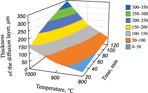
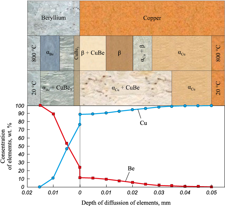
The thickness of the diffusion zone, or weld, was determined as a result of heterodiffusion involving the elements of Be–Cu model pairs, in relation to temperature and welding time (Fig. 2). Analysis of the diagrams reveal that the thickness of the diffusion weld at the Be–Cu joint varies from 26 to 345 μm, with an increase in temperature from 800 to 1000 °C and an extension of the holding time from 20 to 120 min. Theoretical prediction of the phase composition during diffusion welding (Fig. 3) was determined by comparing the concentrations of the components (diffusant and matrix metal) calculated using formulas (1) to (3) with the Be–Cu state diagram.
Fig. 2. Dependence of the thickness of the Be–Cu
Fig. 3. Predicted quality parameters of Be–Cu diffusion welds at t = 20 and 800 °C, |
The calculated layer thickness of the Be–Cu pair during diffusion welding at 800 °C for 2 h measures 65 μm: 15 and 50 μm on the beryllium and copper sides, respectively. It’s worth noting that the formation of intermetallic compounds is possible in the diffusion weld. Under the specified welding conditions (800 °C for 2 h), the resulting diffusion weld exhibits a multiphase structure, as shown in Fig. 3. At its periphery, solid solutions based on beryllium (αBe ) and copper (αCu ), are expected to form, while the СuBe3 intermetallic compound zone and two-phase regions αBe + СuBe3 , βCu + CuBe, αCu + βCu should emerge closer to the initial contact boundary.
Cooling to 20 °C is expected to lead to a reduction in the number of phases. The βCu phase will disappear, and the regions containing copper- and beryllium-based solid solutions will contract. At room temperature, the 65-μm thick diffusion zone, which includes СuBe3 and CuBe intermetallic compounds alongside solid solutions, will remain intact (see Fig. 3).
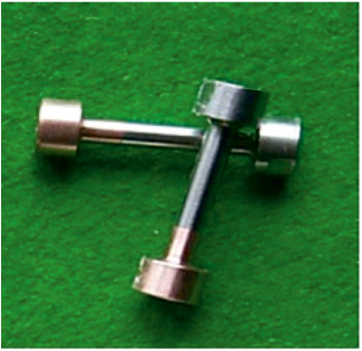
In order to assess the quality of diffusion bonding, an experimental validation was conducted. Cylindrical blanks, each 50 mm in height with a diameter of 100 mm, were fabricated using beryllium grade TGP-56 and M3 copper. After surface cleaning via etching, the Be–Cu cylindrical blocks were assembled. Diffusion welding [24] took place in a laboratory hot-pressing furnace under vacuum conditions (1.33 Pa) at temperatures ranging from 700 to 850 °C for 2 h, all while subject to uniaxial compression at a pressure of 10 MPa. The integrity of each blank’s joint was evaluated based on the outcomes of mechanical tensile tests performed on three samples (as depicted in Fig. 4). The results are provided in the Table below.
Fig. 4. Mechanical test samples
Be–Cu diffusion-welded bimetal samples'
| |||||||||||||||||||||||
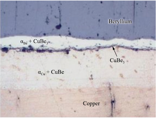
The analysis of the data obtained reveals that, in all cases, the samples were damaged at the juncture of the ingredients intended for welding, where the СuBe3 embrittling intermetallic phase was formed during the diffusion interaction (Fig. 5). For this reason, the level of joint’s mechanical properties did not surpass 50 % of the values for the matrix metal which is beryllium.
Fig. 5. Microstructure (×200) of Be–Cu weld after diffusion welding at t = 800 °C for 2 h |
Therefore, the underlying issue with the designed composite lies in the fact that the Be–Cu zone, which emerges in the weld structure, comprises grains of the CuBe3 intermetallic compound exclusively. This can result in the embrittlement of the welded joint and a subsequent reduction in its mechanical characteristics.
In order to address this structural flaw, further numerical studies were carried out with an aim to employ foil spacers made from metals that readily dissolve in the materials of the diffusion pair. These metals must have a melting point not lower than that of copper and should not form structural single-phase regions consisting solely of intermetallic compounds. The thickness of these spacers is also a critical factor. During the process of heterodiffusion, the spacer’s material should dissolve within the major components (beryllium and copper).
Hence, the decision was made to employ a 10 µm thick nickel foil spacer, which was hypothetically positioned between the beryllium and copper materials. Subsequently, numerical studies were conducted based on the aforementioned algorithm. To calculate diffusion coefficients [27], using the relationships (2)–(7):
| Cu in Ni: \(D = 7.0\,\exp \left( {\frac{{ - 238\,\,{\rm{kJ}}}}{{RT}}} \right)\,,\) | (4) |
| Ni in Cu: \(D = 1.95\,\exp \left( {\frac{{ - 236\,\,{\rm{kJ}}}}{{RT}}} \right)\,,\) | (5) |
| Ni in Be: \(D = 2.24\,\exp \left( {\frac{{ - 247\,\,{\rm{kJ}}}}{{RT}}} \right)\,,\) | (6) |
| Be in Ni: \(D = 0.02\,\exp \left( {\frac{{ - 193\,\,{\rm{kJ}}}}{{RT}}} \right)\,,\) | (7) |
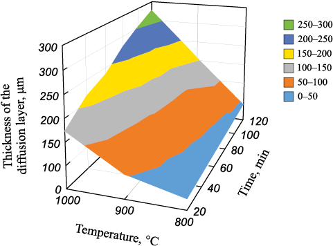
heterodiffusion parameters, including depth, concentration, and the thickness of diffusion zones formed during welding within the temperature range of 800–1000 °C for 20–120 min, were determined employing equation (1) (Fig. 6).
Fig. 6. Dependence of the thickness of the Be–Ni–Cu |
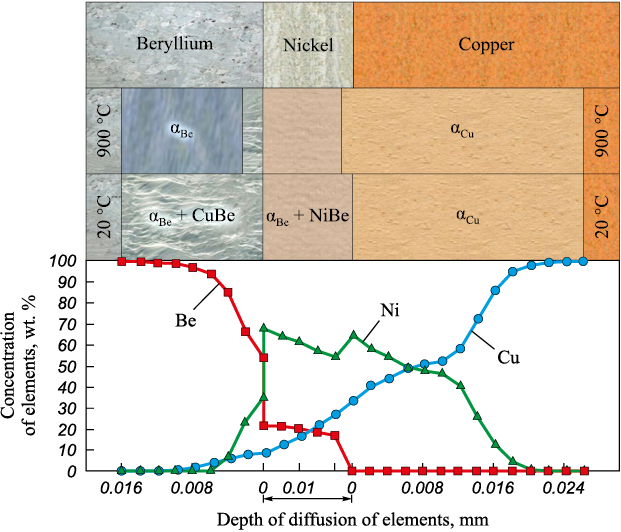
Analysis of the diagrams (refer to Fig. 4 and 6) reveals that a diffusion zone, similar in thickness to the one achieved by Be–Cu welding (at t = 800 °C for 2 h), can be attained by welding with a nickel spacer at t = 900 °C for 20 min. The predicted concentration of elements and the structure of the weld are presented in Fig. 7.
Fig. 7. Predicted quality parameters of Be–Ni–Cu diffusion welds at t = 20 and 900 °C, |
At a welding temperature of 900 °C, the diffusion layer encompasses two zones comprising solid solutions based on copper αCu and beryllium αBe . Additionally, there are two zones with structures reinforced by intermetallic compounds, specifically CuBe and NiBe. However, upon cooling to room temperature, the αBe zone disappears, leaving three distinct structural zones: αBe + CuBe, αBe + NiBe and αCu (refer to Fig. 7).
Notably, what stands out is that the formation of single-phase regions consisting solely of intermetallic compounds is not anticipated in the structure of the diffusion-welded joint. This outcome should be considered a positive effect stemming from the utilization of a nickel spacer in Be–Cu diffusion welding.
Conclusions
Based on the numerical studies and theoretical prediction, the following conclusions can be drawn.
1. When diffusion welding the beryllium-copper model pair at 800 °C for 2 h, a diffusion solidification zone, 65 μm in width, is expected to form. This zone will consist of beryllium-based solid solutions αBe and copper-based solid solutions αCu , two-phase regions αBe + СuBe3 , αCu + CuBe, and a layer of СuBe3 intermetallic compound.
2. The presence of a single-phase region composed of СuBe3 intermetallic compound in the structure of diffusion-welded joint should be considered a detrimental factor that makes the weld brittle and reduces its overall quality.
3. The introduction of a 10 µm thick nickel spacer between the welded beryllium–copper elements allows for the modification of the studied joint by eliminating the single-phase intermetallic region from the weld structure.
4. Following additional experimental validation, the results obtained from the analytical studies can serve as the foundation for a method to theoretically predict the structural and morphological quality of beryllium-copper diffusion-welded joints. This prediction method encompasses phase composition and the size of structural zones within the diffusion welds.
References
1. Dorn C., Vidal E., Goods S. Beryllium materials for fusion reactor wall applications. Proceedings of the 13th International Workshop on Beryllium Technology (BeWS-13). (Narita, Japan, 20–21 September, 2017).
2. ITER blanket, shield and material data base. International atomic energy agency. Iter documentation series. No. 29. Vienna, 1991, 264 p. https://inis.iaea.org/collection/NCLCollectionStore/_Public/23/003/23003898.pdf
3. Pitts R.A., Corpentier S., Escourbiac F., Hirai T., Komarov V., Kukushkin A.S., Lisgo S., Loarte A., Merola M., Mitteau R., Raffray A.R., Shimada M., Stangeby P.C. Physics basis and design of the ITER plasma-facing components. Journal Nuclear Material. 2011;415(1): S957–S964. https://doi.org/10.1016/j.jnucmat.2011.01.114
4. Zucchetti M., Di Pace L., El-Guebali L., Kolbasov B.N., Massaut V., Pampin R., Wilson P.H. The back end of the fusion materials cycle. Fusion Science and Technology. 2009:109–139. https://doi.org/10.13182/FST09-12
5. Gervash A., Mazul I., Yablokov N. Alternative SS/CuCrZr joining methods for ITER. In: ICFRM-10. Baden-Baden, 2001. P. 129–134.
6. Tavassoli A.A. Assessment of austenitic stainless steel. Fusion Engineering and Design. 1995;29:371–390. https://doi.org/10.1016/0920-3796(95)80044-X
7. Asano K., Katsura R., Kawano S., Koshiishi M. Thick plate welding of irradiated stainless steel. Effect of irradiation on materials: In: 19th International Symposium. ASTM STP12443S. 2000. P. 944–958. https://www.doi.org/10.1520/STP12443S
8. Korostelev A., Abramov V., Bashnin A. Assessment of metallurgical quality and mechanical properties of the 316LN-IG steel produced by different technologies. Abstracts 8 International Conference on Fusion Reactor Materials, October 26–31, 1997, Sendai, Japan. P. 207.
9. Ivanov A.D., Nikolaev A.K., Kalinin G.M, Rodin M.E. Effect of heat treatment on the properties of CuCrZr alloys. Journal Nuclear Material. 2002;307-311(1):673–676. https://doi.org/10.1016/S0022-3115(02)01110-8
10. Gervash A., Mazul I., Yablokov N., Ganenko A. Comparative strength analysis and therma fatigue testing of Be/CuCrZr and Be/GlidCop joints produced by fast brazing. Fusion Technology. 2000;38(3):278–282.
11. Kolbasov B.N., Khripunov V.I., Biryukov A.Yu. Some thoughts about beryllium resources, impurities in it and necessity of its detritiation after irradiation. Voprosy atomnoi nauki i tekhniki. Seriya: Termoyadernyi sintez. 2013;36(4):3–12. (In Russ.).
12. Barabash V., Eaton R., Hirai T., Kupriyanov I., Nikolaev G., Zhanhong Wang, Xiang Liu, Roedig M., Linke J. Beryllium qualification activity for ITER first wall applications. In: 13th International Workshop on Plasma-Facing Materials and Components for Fusion Applications / 1st International Conference on Fusion Energy Material Science (Rosenheim, Germany, 09–13 May, 2011). P. 3–12.
13. Kupriyanov I.B., Khomutov А.M., Nikolaev G.N., Gorlevsky V.V., Markushkin Yu.E., Chakin V.P., Gervash A.A., Kalashnikov A.N., Kolbasov B.N. Status of beryllium R&D activities in Russian Federation. In: Proceedings 7th IEA International Workshop on Beryllium Technology (Santa Barbara, California, USA, 29 November – 2 December 2005). Р. 8–16.
14. Frants Ye., Kolmakov M., Zorin B., Kylyshkanov M., Podoinikov M., Udartsev S., Vechkutov A., Vladimirov P., Chakin V., Gaisin R. Beryllides – experience of UMP JSC in development and testing. In: Proceedings of the 15th International Workshop on Beryllium Technology (BeWS-15) (Karlsruhe, Germany, 14–15 September, 2022). P. 52–61. http://dx.doi.org/10.5445/KSP/1000156312
15. Zmitko M., Vladimirov P., Chakin V., Spagnuolo A.G. The HCPB test blanket module: current status in development and qualification of beryllium materials and an overview of open issues. In: Proceedings of the 15th International Workshop on Beryllium Technology (BeWS-15) (Karlsruhe, Germany, 14–15 September, 2022). P. 6–19. http://dx.doi.org/10.5445/KSP/1000156312
16. Smith K., Frehn A. Overview of the United States beryllium industry – 2022 Update. In: Proceedings of the 15th International Workshop on Beryllium Technology (BeWS-15) (Karlsruhe, Germany, 14–15 September, 2022). P. 36–51. http://dx.doi.org/10.5445/KSP/1000156312
17. Belyakov V., Mazul I., Strebkov Yu. Manufacturing and testing of large-scale mock-ups of ITER plasma facing components in Russia. Fusion Engineering and Design. 2002;61–62:129–134. https://doi.org/10.1016/S0920-3796(02)00225-9
18. Gervash A., Giniyatulin R., Mazul I., Watson R. Beryllium armoured mock-ups for fusion high heat flux application. In: Proceedings of the 20th SOFT. Marseille, France, 1998. Р. 47–50.
19. Gervash A., Giniyatulin R., Komarov V., Mazul I. Comparative thermal cyclic testing and strength investigation of different Be/Cu joints. Fusion Engineering and Design. 1998;(39–40):543–549.
20. Gervash A., Mazul I., Belyakov V., Yablokov N. Manufacturing and testing of Be first wall mock-up for ITER. In: 5 IEA Workshop on Beryllium technologies for fusion. Perspektivnye materiali. Special issue. Moscow; Interkontakt Nauka, 2002.
21. Lyshinsky A.V. Diffusion welding of dissimilar materials. Moscow: Izdatelskii Tsentr «Academiya», 2006. 208 р. (In Russ.).
22. Trykov Yu.P., Gurevich L.M., Arisova V.N. Diffusion in layered composites. Volgograd: RPK «Polytechnik», 2006. 402 р.
23. Barwinok V.A., Bordakov P.A., Mordasov V.I., Usoltsev A.L., Oleksiyko S.M. Increasing the strength of joints made of dissimilar materials during diffusion welding and soldering. Problemy mashinostroenija i avtomatizatsii. 1999;3:79–83. (In Russ.).
24. Gervash A., Mazul I., Litunovsky N., Pokrovsky A. Thermal fatigue properties and results of in-pile integrated test of Be/CuCrZr and Be/GlidCop joints produced by fast brazing. In: Sb. tr. V rabochei gruppy Mezhdunarodnogo Energeticheskogo Agenstva po berilliyu. Perspektivnie Materialy. Special issue. Moscow: Interkontakt Nauka, 2002. P. 44–47.
25. Ananyin V.M., Gladkov V.P., Zotov V.S., Skorov D.M. Diffusion processes in beryllium. Moscow: Energoatomizdat, 1981. 75 р. (In Russ.).
26. Powder metallurgy. Sintered and composite materials (Ed. V. Shatt). Moscow: Metallurgiya, 1983. 520 р. (In Russ.).
27. Diffusion welding of materials. Directory (Ed. Kazakov N.F.). Moscow: Mashinostroenie, 1981. 271 р. (In Russ.).
28. Papirov I.I. Structure and properties of beryllium alloys: Directory. Moscow: Energoizdat, 1981. 367 р. (In Russ.).
About the Authors
B. V. SyrnevKazakhstan
Boris V. Syrnev – Dr. Sci. (Eng.), Leading Researcher at Research Center “Veritas”
19 Serikbaev Str., Ust-Kamenogorsk 070004, Kazakhstan
O. I. Maslennikov
Kazakhstan
Oleg I. Maslennikov – Leading Process Engineer at Research Center “Veritas”
19 Serikbaev Str., Ust-Kamenogorsk 070004, Kazakhstan
O. V. Semilutskaya
Kazakhstan
Oksana V. Semilutskaya – Senior Lecturer at the School of Metallurgy and Mineral Processing
19 Serikbaev Str., Ust-Kamenogorsk 070004, Kazakhstan
Review
For citations:
Syrnev B.V., Maslennikov O.I., Semilutskaya O.V. Establishing theoretical foundations for predicting the structural and morphological characteristics of diffusion-welded joints of the beryllium–copper composite. Powder Metallurgy аnd Functional Coatings (Izvestiya Vuzov. Poroshkovaya Metallurgiya i Funktsional'nye Pokrytiya). 2024;18(2):14-22. https://doi.org/10.17073/1997-308X-2024-2-14-22


