Scroll to:
Investigation of influence of technological parameters on the properties of SiC samples fabricated by selective laser sintering. Part 1
https://doi.org/10.17073/1997-308X-2024-3-71-84
Abstract
The paper describes experiments on selective laser sintering (SLS) of a high-temperature ceramic material – silicon carbide powder F320 – using the MeltMaster3D-160 SLS unit equipped with a fiber ytterbium laser with a peak power of 200 W. We investigated the sintering mechanism and the impact of technological parameters on the microstructure, phase composition, and density of the resulting 3D cubic samples. The technological properties of the initial powder were also investigated, including morphology, granulometric composition, bulk density, and flow rate. The powder morphology mainly consists of acicular particles with an aspect ratio of 1:5. Granulometric analysis revealed an average particle size of 48 μm. Measurements indicated that the bulk density reached 1.11 ± 0.01 g/cm3, approximately 36.6 % of the theoretical density value. The average time of powder outflow from the Hall funnel was 21.0 ± 0.1 s, with 2–3 hits on the funnel during the measurement process. Experimental cubic samples of 10×10 mm were manufactured using 75 technological modes. Silicon carbide powder particles sinter due to the thermal effect of laser radiation and the release of SiC microparticles on the surface of the powder particles, with silicon (average size less than 1 μm) prevailing in the composition, followed by mutual bonding of neighboring powder particles in the sintering region. X-ray phase analysis demonstrated that due to the laser radiation, the resulting 3D samples contain the following phases: SiC (6H), Si, and C. It was revealed that a scanning step larger than the actual spot diameter (spot diameter + thermal influence zone), 60–70 μm in size, causes the formation of unsintered areas between sintering tracks. The key parameters affecting the density index of the obtained samples are layer height, energy density, and scanning step. The best density index for the obtained samples is 86.7 % relative to the absolute density of the material (3.21 g/cm3). Further research will be devoted to the development of techniques for post-processing the resulting porous samples-blanks to obtain a density close to 100 %.
Keywords
For citations:
Bubnenkov B.B., Zharmukhambetov A.S., Ivanov I.A., Yudin A.V., Taktashev A.E., Starkov A.M., Sharapov I.S., Alekseeva E.M. Investigation of influence of technological parameters on the properties of SiC samples fabricated by selective laser sintering. Part 1. Powder Metallurgy аnd Functional Coatings (Izvestiya Vuzov. Poroshkovaya Metallurgiya i Funktsional'nye Pokrytiya). 2024;18(3):71-84. https://doi.org/10.17073/1997-308X-2024-3-71-84
Introduction
Silicon carbide materials are used in various industries, including manufacture of critical duty products. This is due to their high compressive strength, dimensional stability, wear and heat resistance, thermal conductivity, heat stability, as well as chemical and radiation resistance. The listed properties determine their use as a material for gas turbine engine nozzles, bearings, working units of chemical pumps, atomizers, burners, cutting tools, pipelines, heat exchangers, heaters, and other critical applications.
The operating temperature range of pure silicon carbide material reaches t = 1400÷1500 °C in air, and when high-temperature coatings are applied, it increases to 2000 °C and higher (depending on the type of coating, the aggressiveness of the oxidizing environment and the operating time) [1]. More technologically advanced composite silicon carbide materials, such as RS–SiC, can be operated in air at temperatures up to 1350 °C [2].
The bulk of silicon carbide products are manufactured by: simple sintering; activation sintering at t ≈ 1600÷1800 °C of workpieces initially pressed from powder with sintering additives (Al2O3 , Y2O3 , Si3N4 and etc.); reaction sintering; hot pressing (HP); hot isostatic pressing (HIP); spark plasma sintering (SPS) – one of the types of hot pressing [3–5]. When HP and its varieties are used for molding products, silicon carbide powder in combination with sintering additives are applied to intensify compaction processes [3; 4; 6]. The process key features are high sintering temperature ~1700÷2000 °C and pressure of ~50÷70 MPa [3–5], while the exposure can take several hours. The methods based on HP are characterized by high performance, but they are limited to manufacturing products of simple geometric shapes and require the previous stage when an individual mold is fabricated for a specific part.
Additive technologies (AT) have an undeniable competitive edge over traditional ones, including fabricating products with complex geometries (branched topology), thin-walled products and the ones with closed cavities, which enables to solve a wide range of new design issues in the framework of modernization of the energy complex, military and space industries. There are direct and indirect At methods for manufacturing ceramic products.
The direct methods are the ones that require one stage to obtain a finished product – the product is manufactured on an additive unit with minimal subsequent mechanical processing or without it. Typically, the objective is to obtain completely dense products or the ones with a density of minimum 98 %. The following methods can yield this result: selective laser sintering (SLS) technology – selective layer-by-layer laser sintering of ceramic powder; micro-SLS process, which uses a laser scanning spot that is 2–3 times smaller than in traditional SLS [7]; SLS of a mixture of ceramic powder with a more fusible component, for example silicon, which ensures that during the sintering process, the pores of each of the product layers are filled [8]. The advantage of this approach is that it requires less production time and fewer resources due to reduced process steps.
Indirect methods include one or more operations for post-processing of a workpiece manufactured by the additive method. Post-processing typically includes 3 additional stages:
1) impregnation with a reagent;
2) reagent pyrolysis to form an additional carbon or silicon carbide framework;
3) molten silicon infiltration to ensure compaction and form the secondary silicon carbide as molten silicon interacts with free carbon released from the reagent [9].
Indirect methods include: selective layer-by-layer SLS of a mixture of ceramic and polymer powders followed by pyrolysis and molten silicon infiltration; SLS of a mixture of ceramic powder and elements that form the main component during post-processing [10], followed by impregnation with polymer to fill the remaining pores, pyrolysis and silicon infiltration; light stereolithography (SLA) – selective layer-by-layer curing of a mixture of photopolymer and base material powder using a light source, followed by pyrolysis and silicon infiltration [11–14]; selective layer-by-layer binding of powder material (binder jetting – BJ) – applying glue on the powder layer, followed by pyrolysis and silicon infiltration [15–18]; extrusion (direct ink writing – DIW) of material (ceramic paste = powder + binder) using a print head, layer by layer, followed by pyrolysis and silicon infiltration [19–23].
With regard to the production of ceramic structural materials, direct and indirect SLS has a number of advantages compared to other 3D printing method:
– fewer resources are required to prepare initial materials as powder components of the composition are used in their pure form and can be further processed and mixed under certain modes in specific proportions to obtain the required properties of the final product;
– minimum shrinkage coefficient relative to the CAD model that ensures high-accuracy manufacture of complex-profile products, including thin-walled ones;
– reduced free silicon content as a result of post-processing using reaction sintering technology, which helps to enhance the product strength and dimensional stability;
– reduced content of a polymer binder with a high carbon residue (if used), which during subsequent post-processing (pyrolysis) decreases stress across the cross-section of the workpiece during polymer decomposition, in contrast to BJ and SLA, which require significantly larger amount of binder for effective bonding of particles without high temperature, complicating the manufacture of thick-section and complex-profile products and causing problems with selecting the optimal post-processing parameters.
The advantages of SLS will significantly expand the range of products to synthesize from refractory, heat-, corrosion- and radiation-resistant materials based on silicon carbide, in terms of increased complexity of their geometry and topological optimization, and will also considerably reduce the amount of mechanical processing, which is critical for products with internal geometry and cavities where mechanical operations are difficult or impossible.
This technology is intended for manufacturing parts and components of nuclear and thermal energy equipment operating in aggressive environments at high temperatures and pressures, for example, advanced reactors with molten salt as coolant (MSR) and acidic coolants (in alkaline coolants, residual silicon will transform into silicates and pollute it), as well as the equipment used in other fields.
We conducted a number of initial experiments to obtain samples from SiC using the direct SLS method and proved that 3D samples can be obtained using a Russian-made MeltMaster3D-160 unit (JSC SPA CRIMET, Moscow) from silicon carbide-based powder material produced by JSC “SRI SIA “LUCH” (Moscow). We also studied the impact of the unit technological parameters on the properties of the resulting samples.
The research was based on domestic and foreign experience in selective laser sintering of ceramic materials; the parameters for manufacturing samples were adjusted taking into account the characteristics of the unit and the materials used. The unit design was elaborated as the technological parameters for SiC-based material were developed.
For the first time, 3D silicon carbide samples were obtained using unconventional part construction modes. Based on the findings of the analysis, we provide recommendations on improving the manufacturing parameters to enhance the properties of the resulting samples.
Materials and methods of the experiment
Silicon carbide powder, graded F320 according to FEPA standard, served as the initial material for selective laser sintering.
The flow rate of powder was determined using a calibrated Hall funnel (according to GOST 20899-98). The prepared portion of the powder was poured into a funnel with a 5-mm outlet hole. In accordance with the standard, three measurements were made from three 50-g portions of powder.
Bulk density was assessed using a Scott volumeter. According to GOST 19440-94, three measurements were performed on three portions of powder from a sample with a volume of 100 cm3.
To determine the average particle size, as well as the particles distribution curve, a Laser Particle Sizer Analysette 22 MicroTec plus (Fritsch GmbH, Germany) was used in accordance with GOST R 8.777-2011. The measurements were conducted using a dispersion unit in a liquid medium, designed for measuring solid materials and suspensions in a liquid, mainly aqueous, medium. 2–3 measurements of the granulometric composition of the powders under study were performed and the results were averaged. The shape and size of the particles were assessed using a Neophot 21 microscope (Carl Zeiss Jena, Germany) according to GOST 25849-83.
During the incoming inspection at the delivery stage and during the repeated circulating powder sieving, an ASV-200 sieve analyzer (NPK Mekhanobr-Tekhnika, St. Petersburg) with a set of sieves with a nominal value of 100 and 56 µm was used to separate the target fraction.
Before the SLS process, moisture was removed from the powder by drying it in an NK 7.7.7/3.5 oven (JSC Nakal – Industrial furnaces, Solnechnogorsk) at a temperature of 70–100 °С.
MeltMaster3D-160 unit made in Russia (JSC SPA CRIMET, Moscow) was used for SLS. The main characteristics of the unit: laser type – fiber; laser power – from 5 to 200 W; laser spot size – from 50 to 150 µm; scanning step – from 10 to 150 µm; scanning speed – from 50 to 1500 mm/s; approach increment of the construction platform – from 10 to 200 µm; protective atmosphere – nitrogen/argon/helium; platform heating – up to 120 °C; working area for sintering a part – 160×160×200 mm. Argon of purity 6.0 (99.9999 %) was used as the working gas.
Preparation for SLS. The powder was dried at a temperature of 100 °C before selective laser sintering of the samples.
To prepare and support the layer-by-layer prototyping of experimental samples on MeltMaster3D-160 unit, we used 3Ddigit specialized software package (JSC SPA CRIMET, Moscow) designed for placing a 3D model relative to the construction platform, forming supporting structures, setting technological parameters, cutting a 3D model into layers and generating the control code. The software functionality is responsible for automating all stages of layer-by-layer synthesis based on the original 3D model.
Additive production of samples using the SLS method includes the following steps:
– setting technological parameters in the software;
– checking the 3D model for integrity and correcting errors;
– placing the 3D model relative to the technological platform;
– creating technological support for the model;
– cutting a 3D model into layers;
– generating the control code;
– SLS process.
During preparation for printing, the working chamber was filled with an inert gas – argon, which enables to process reactive materials. Reliable filtration and efficient circulation provided by the system of blowers ensure a high degree of gas purity. Thus, the selective laser sintering of laboratory sample blanks was performed in an argon atmosphere with a stable residual oxygen concentration of less than 700 ppm, to avoid the formation of SiO2 under high-temperature laser action.
SLS process. Based on the analysis of domestic and foreign literary sources on SLS of ceramic materials, the initial set of parameters for the unit operation was selected, which was gradually changed based on the analysis of the microstructure and density of the resulting samples.
Experimental cubic samples of 10×10 mm were manufactured using 75 technological modes in order to study the impact of SLS process parameters on their density and microstructure. The following parameters were changed: laser power (P) in the range from 30 to 190 W, scanning speed (V) – from 100 to 1000 mm/s, scanning step (d) – the distance between tracks (line marks) – in the range from 20 to 150 µm, layer thickness (h) – from 20 to 60 µm. The combination of these parameters forms the energy density (E) of laser radiation:
\[E = \frac{P}{{Vhd}}.\]
The density of the manufactured samples was measured on Discovery DV215CD balance (OHAUS Corporation, USA) using the hydrostatic method according to GOST 25281-82 “Powder metallurgy. Method of determination of formings density”. First, the mass of the sample in air was determined. Then the sample was covered with a thin protective layer of vaselene to isolate the surface pores and to avoid the formation of near-surface air bubbles, and its mass in air was measured again. The next step was weighing in distilled water at a fixed temperature. Based on the measurement results, the density of the samples was calculated taking into account the density of vaselene, water and air.
Microstructural studies and EDS analysis were performed using a Zeiss EVO 50 XVP scanning electron microscope (Carl Zeiss AG, Germany) with an attachment for energy dispersive analysis to determine the patterns of sintering and the impact of technological parameters on the microstructure of the resulting samples.
The D8 Discover diffractometer (Bruker Optic GmbH, Germany) with CuKα-radiation was used to perform X-ray phase analysis in order to determine the final phase composition of the samples and to confirm the impact of manufacturing parameters on the phase composition. Bruker AXS DIFFRAC.EVA v. 4.1 software and ICDD PDF-2 international database were used for phase identification.
Results and discussion
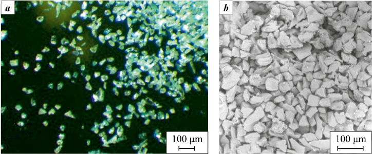
The morphology of silicon carbide powder particles was analyzed using several visual fields (Fig. 1).
Fig. 1. Morphology of SiC powder (F320) |
When viewed under a light microscope, SiC particles look like transparent green crystals without pores or inclusions (Fig. 1, а). Most of the particles are non-spherical and have a non-equiaxial/non-spherical or splintered shape; acicular particles with an aspect ratio up to 1:5 are also observed (Fig. 1, b). Some particles are joined into agglomerates, their size is larger than that of most particles. This morphology of particles cannot provide good flow rate or ensure the formation of a uniform powder layer. Also, such morphology will affect the density characteristics of the resulting samples.
The agglomerates and non-equiaxial particles negatively affect the sintering characteristics of the material. The tendency to agglomerate is a natural property of powder particles, and the more non-equiaxed their shape is, the higher the tendency to agglomerate. Large agglomerates interfere with the process of “healing” pores during the sintering process, since the driving forces – their direction and speed – of the particles inside the agglomerate will significantly differ from those of the particles next to it. This difference leads to significant internal stresses, emergence of large pores or even the formation of microcracks. The dimensions of such defects and the resulting structural heterogeneity directly determine the density, strength and other properties of the material.
For this reason, before being used for the SLS process, the powder should be classified to recover the target fraction <60 μm by screening off large particle agglomerates.
Study of the granulometric composition. The powder particles distribution was obtained (Table 1).
Table 1. Granulometric composition of SiC powder F320
|
Table 1 shows that the average particle size of silicon carbide powder F320 under study, in the as-delivered condition is 48.2 μm. After 25 series of production processes, it slightly increases (by 7.2 µm) to 55.4 µm.
The sizes of fractions vary from 5 to 110 µm – this wide range is attributed to the powder particles being non-equiaxed and having a splintered or acicular shape. This spread is not a typical particle size distribution for the units operating based on the SLS method (20–63 μm), which can contribute to the formation of defects such as pores and voids and adversely affect the sample manufacturing process. Therefore, the target fraction <60 µm was recovered from the total mass of the powder by screen sizing. Acicular particles cannot be removed from screen sizing using the sieve analysis. However, to be used in additive technologies, including SLS, these particles should be separated, and the remaining particles should be spheroidized, if possible.
Determination of the flow rate. The average time of the powder outflow from the Hall funnel could not be determined, since the outflow spontaneously stopped. Next, based on the standard, the funnel was hit once, but after some time the outflow of powder stopped. According to the standard, it means that the flow rate of the powder does not conform with the test method described in this standard.
Determination of bulk density. The bulk density of powders that do not flow spontaneously from a funnel with a hole 5 mm in diameter is measured using a volumeter according to GOST 19449-94.
The analysis of the bulk density of silicon carbide powder F320 showed that its average value (1.11 ± 0.01 g/cm3) accounts for ~36.6 % of the theoretical density of this material (the vibro-compacted density being 45 %). This bulk density value can be attributed to the fact that the powder contains a significant amount of acicular particles with a large aspect ratio and splintered particles: the former contribute to the emergence of “bridges” with voids underneath, while the latter, due to their roughness, additionally prevent powder distribution and its free spreading during layer formation.
The set of characteristics and properties of the powder used is presented below:
Average particle size, µm . . . . . . . . 48 ± 0.5
Flow rate, s . . . . . . . . . . . . . . . . . . . . . None1
Bulk density, g/cm3 . . . . . . . . . . 1.11 ± 0.01
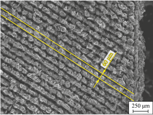
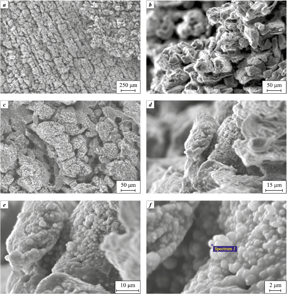
Microstructural studies. Determining the size of the laser spot area and the effective scanning step. As a result of microstructural studies (Fig. 2), it was revealed that the scanning step is larger than the actual spot diameter (spot diameter + heat-affected zone), which is 60–70 μm (Fig. 3), causes the formation of unsintered regions between the tracks. The width of these areas is comparable to the difference between the step size and the laser spot diameter. The unsintered regions significantly affect the samples density, as evidenced by the results of density determination.
Fig. 2. Impact of the scanning step (d) on the sintering
Fig. 3. Width of a single sintering zone as SiC powder |
This effect may be associated with high thermal conductivity of the material, which prevents accumulation of the thermal energy in the scanned area (laser beam path) and its transfer to neighboring areas outside the spot diameter, where there was no direct exposure to laser radiation, as it was the case with metal powders. Laser radiation sinters powder particles to form a sintered region only in the area directly exposed to the laser spot + 5÷10 µm, then the heat flow follows the path of least resistance or, in other words, moves in the direction with greater thermal conductivity than that of freely poured powder. For this reason, thermal energy is most actively absorbed in the vertical direction by the previous, already sintered monolithic layers, which are denser and more thermally conductive compared to the area of unsintered powder surrounding the part and acting as a heat insulator with a relatively small degree of thermal absorption.
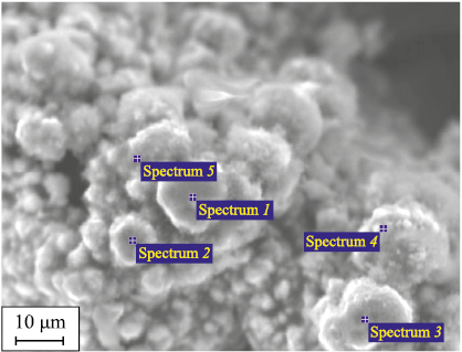
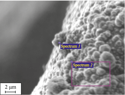
Sintering mechanism. Fig. 4 shows microphotographs of the surface of SiC powder particles after sintering in the resulting samples. Upon a detailed examination of the surface of the original powder particles, one can note that microparticles are formed, 1–7 μm in size, the shape being close to spherical, but with an uneven surface. They have a lighter shade than the particles of the original powder. These microparticles form clusters – areas with an increased number of cluster-shaped defects – on the surface of the original powder particles (including at the points of contact between them). The predominant size of the resulting microparticles is less than 1 µm. Thus, we can conclude that after laser sintering, more defects emerge on the surface of the original powder particles.
Fig. 4. Scaled representation of the mechanism of laser sintering of SiC powder particles |
It can be assumed that short-term high-temperature exposure of the SiC powder surface to laser radiation result in local overheating and micromelting with partial SiC decomposition. This assumption is also made in [24]. Further, as the locally overheated area cools down, the oval and spherical microparticles, lighter in color than SiC powder, form. They have a size of 1–7 μm, sometimes less than 1 μm, and a chemical composition identical to that of silicon carbide, with silicon prevailing, as evidenced by the results of EDS analysis given in Table 2.
Table 2. Results of EDS analysis of the surface
| |||||||||||||||||||||||||||||||||||||||||||||||||||||||||||||||
The SiC decomposition temperature is 2730 °C, and the Si and C melting temperatures are 1414 and 3367 °C, respectively. At the same time, in accordance with reference data [25], the vapor pressure of 100 kPa (~1 atm) is set at temperatures of 2613 and 4985 °C for silicon and carbon, respectively. Therefore, when exposed to laser radiation, SiC powder presumably decomposes, while silicon simultaneously melts and evaporates. At the next stage, in accordance with the phase diagram, in the Si–C system the phase equilibrium during crystallization will shift to the “SiC + graphite” region.
There are two assumptions why oval and spherical precipitates with silicon dominating in the composition form: the first one is that ultra-fast cooling of the melt with undissolved graphite results in the formation of microparticles of non-stoichiometric SiC(1–x) depleted in carbon; the second is that silicon sweats out on the surface from the depths of the melt bath. Starting from the stage of SiC decomposition, Si concentrates in the near-surface zone and evaporates from the melt bath. When crystallization, initiated from the bath surface, starts, Si continues to sweat out, since the deep layers in contact with the bath are heated due to the high thermal conductivity of SiC.
Thus, during SLS of SiC powder, the sintering driving force is not the system (powder particles) striving to minimize surface energy and transit to a more equilibrium state, that is, to acquire a more spherical shape, reduce defects and gradually move towards the state of reciprocal slipping and consolidation. On the contrary, the interaction regions are formed at the contact boundary of powder particles from the more low-melting phase. These regions account for reciprocal slipping of powder particles during compaction and, at the final sintering stage as they cool down, they are “bound” as more defective cluster-like structures emerge at the point of contact and on the “free” surface of the particles, in contrast to the less defective morphology of the particles before exposure to laser radiation (see Fig. 1). It should also be noted that compaction during sintering is not facilitated by the curvature of the surface of splintered SiC powder particles, which reduces the density of the initial layer and further compaction during mutual slipping of particles under the influence of laser radiation.
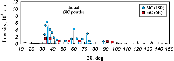
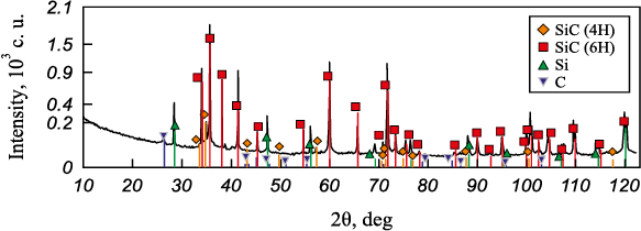
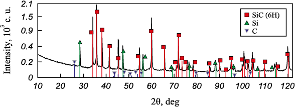
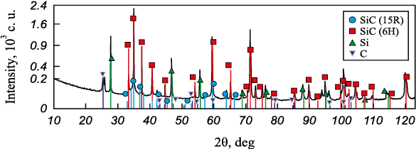
X-ray phase analysis. XRF was performed to determine the phase composition of the initial SiC powder, as well as to identify patterns of the impact of laser radiation on the composition of phases in samples after SLS. The results of X-ray phase analysis are presented in Table 3.
Table 3. Phase composition of the initial SiC powder and SiC samples
| ||||||||||||||||||||||||||||||||||||||||||||||||||||||||||||||||||||||||||||||||||||||||||||||||||||||||||||||||||||||||||||||||||||||
The samples revealed silicon Si, silicon carbide with a hexagonal crystal lattice of SiC (6H), traces of modification of SiC with a hexagonal lattice of SiC (4H), as well as (in some samples) traces of modification of silicon carbide with a rhombohedral lattice of SiC (15R), the position of flat layers in the structure of which it is repeated every third layer, not every second one, as in the hexagonal modification.
Also, the SiO2 phase was detected in some samples, which may be due to insufficient oxygen purity of the working atmosphere or to the initial quality of the supplied powder. However, this phase was not identified during incoming inspection, from which we can conclude that it probably emerged during the SLS process at the early stages, when the first layers of the sample were formed.
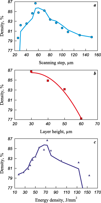
Determination of the density of SLS samples. Our objective was to determine the impact of the unit technological parameters on the properties of the resulting samples, including the relative density. For this purpose, during the experiments, we performed statistical analysis, which revealed that the parameters such as speed (V), scanning step (d) and the height (thickness) of the layer (h) exert a decisive influence on the density of the resulting samples.
Based on the experimental data obtained, the graphs were plotted to show dependence of the samples’ relative density on the technological parameters – scanning step, layer height and energy density (Fig. 5). It has been established that the density of the samples depends nonlinearly on the scanning step – as the scanning step increases, so does the density, reaching a peak at d = 50÷70 μm, and then it reduces. It is important that for this material, the scanning step significantly affects the density of the samples and cannot be considerably increased with a decrease in scanning speed due to the thermophysical properties of the material. On the contrary, there is a linear dependence of the samples’ density on the layer height – as the height increases, the density reduces. Speaking about the impact of the layer height, we should note the stage-by-stage selection of the optimal value of this parameter. The choice of h = 30 μm contributed to higher density of the samples and lower delamination between the sintered layers. There is a certain peak value for the energy density, as well as for the scanning step, after which these values plummet, which is also typical for other materials [26; 27].
Fig. 5. Main dependences of the density of silicon carbide samples |
The best density index for the obtained samples is 86.7 % relative to the absolute density of the material (3.21 g/cm3). This result exceeds the values of foreign studies of previous years, and is also consistent with the data of foreign publications [28–31]. It should be noted that we used pure SiC powder without a binder and the shape of the powder particles had a large aspect ratio (up to 1:5). Despite this, we succeeded in achieving fairly high density values of the resulting samples given the material and technique used. In the future, the samples density can be increased by refining the unit and manufacturing parameters, improving the composition and quality of the initial materials, as well as by developing the technique for post-processing of the resulting samples.
Conclusions
1. This study proved that samples-blanks can be formed from silicon carbide powder by the SLS method without using a binder. The resulting SLS blanks have a density of up to 86.7 %, which can be increased by subsequent reaction sintering at temperatures from 1600 to 1800 °C.
2. A set of technological parameters affecting the properties of the resulting samples was determined: scanning speed, scanning step and layer height.
3. One of the factors limiting an increase in the samples density is the combination of properties of the initial powder material – particle morphology and a wide size range, which results in insufficient density when the layer is formed. As a consequence, additional pores emerge after SLS.
4. When exposed to laser radiation, the silicon carbide powder particles sinter due to the decomposition of SiC (6H; 15R) into C, Si and SiC of another modification (4H), as confirmed by X-ray diffraction data. However, it should be noted that, according to EDS data, non-stoichiometric SiC(1–x) , with silicon prevailing in the composition, can form. Decomposition products are present on the surface of the original powder particles in the form of microparticles with an average size of less than 1 µm. The formation of more low-melting phases Si and, probably, SiC(1–x) on the surface of the initial powder result in mutual slipping and compaction of powder particles in the sintering region, followed by relative binding during crystallization.
5. Further research will involve improvement of the technological characteristics of the initial materials and development of the technique for post-processing of the samples obtained during SLS.
References
1. Droillard C., Lamon J. Fracture toughness of 2‐D woven SiC/SiC CVI‐composites with multilayered interphases. Journal of the American Ceramic Society. 1996; 79(4):849–858. https://doi.org/10.1111/j.1151-2916.1996.tb08516.x
2. Gnesin G.G. Silicon carbide materials. Moscow: Metallurgiya, 1977. 215 p. (In Russ.).
3. Šajgalík P., Sedláček J., Lenčés Z., Dusza J., Lin H.-T. Additive-free hot-pressed silicon carbide ceramics – A material with exceptional mechanical properties. Journal of the European Ceramic Society. 2016;36(6):1333–1341. https://doi.org/10.1016/j.jeurceramsoc.2015.12.013
4. Hayun S., Paris V., Mitrani R., Kalabukhov S., Dariel M.P., Zaretsky E., Frage N. Microstructure and mechanical properties of silicon carbide processed by Spark Plasma Sintering (SPS). Ceramics International. 2012;38(8): 6335–6340. https://doi.org/10.1016/j.ceramint.2012.05.003
5. Li J.F., Sugimoto S., Tanaka S., Esashi M., Watanabe R. Manufacturing silicon carbide microrotors by reactive hot isostatic pressing within micromachined silicon molds. Journal of the American Ceramic Society. 2004;85(1):261–263. https://doi.org/10.1111/j.1151-2916.2002.tb00077.x
6. Saleem A., Zhang Y., Gong H., Majeed M.K. Fluoride doped SiC/Si3N4 composite as a high thermal conductive material with enhanced mechanical properties. Ceramics International. 2019;45(16):21004–21010. https://doi.org/10.1016/j.ceramint.2019.06.289
7. Streek A., Regenfuss P., Ullmann F., Hartwig L., Ebert R., Exner H. Processing of silicon carbide by laser micro sintering. In: 2006 International Solid Freeform Fabrication Symposium (17th Solid Freeform Fabrication Symposium, Austin, Texas, USA,14–16 August 2006). 2006. P. 349–358. https://doi.org/10.26153/tsw/7144
8. Song S., Gao Z., Lu B., Bao C., Zheng B., Wang, L. Performance optimization of complicated structural SiC/Si composite ceramics prepared by selective laser sintering. Ceramics International. 2019;46(1):568–575. https://doi.org/10.1016/j.ceramint.2019.09.004
9. Pelanconi M., Colombo P., Ortona A. Additive manufacturing of silicon carbide by selective laser sintering of PA12 powders and polymer infiltration and pyrolysis. Journal of the European Ceramic Society. 2021; 41(10):5056–5065. https://doi.org/10.1016/j.jeurceramsoc.2021.04.014
10. Zhang K., Zeng T., Xu G., Cheng S., Yu S. Mechanical properties of SiCp/SiC composite lattice core sandwich panels fabricated by 3D printing combined with precursor impregnation and pyrolysis. Composite Structures. 2020;240:112060. https://doi.org/10.1016/j.compstruct.2020.112060
11. Tang J., Guo X., Chang H., Hu K., Shen Z., Wang W., Liu M., Wei Y., Huang Z., Yang Y. The preparation of SiC ceramic photosensitive slurry for rapid stereolithography. Journal of the European Ceramic Society. 2021; 41(15):7516–7524. https://doi.org/10.1016/j.jeurceramsoc.2021.08.029
12. Bai X., Ding G., Zhang K., Wang W., Zhou N., Fang D., He R.. Stereolithography additive manufacturing and sintering approaches of SiC ceramics. Open Ceramics. 2021;5:100046. https://doi.org/10.1016/j.oceram.2020.100046
13. Ding G., He R., Zhang K., Zhou N., Xu H. Stereolithography 3D printing of SiC ceramic with potential for lightweight optical mirror. Ceramics International. 2020;46(11B):18785–18790. https://doi.org/10.1016/j.ceramint.2020.04.196
14. Chen R., Lian Q., Li D., He X., Wang S., Zhuang J. Stereolithographic additive manufacturing diamond/SiC composites with high thermal conductivity for electronic 3D-packaging applications. Ceramics International. 2021;47(10A):14009–14020. https://doi.org/10.1016/j.ceramint.2021.01.270
15. Thomas J., Banda M., Du W., Yu W., Chuang A., France D.M., Singh D. Development of a silicon carbide ceramic based counter-flow heat exchanger by binder jetting and liquid silicon infiltration for concentrating solar power. Ceramics International. 2022;48(16):22975–22984. https://doi.org/10.1016/j.ceramint.2022.04.269
16. Feng K., Hu S., Li L., Mao Y., Heng Y., Yuan J., Wu J., Wei Q. Preparation of low residual silicon content Si–SiC ceramics by binder jetting additive manufacturing and liquid silicon infiltration. Journal of the European Ceramic Society. 2023;43(13):5446–5457. https://doi.org/10.1016/j.jeurceramsoc.2023.05.038
17. Oh J.-W., Park J., Nahm S., Choi H. SiC–Si composite part fabrication via SiC powder binder jetting additive manufacturing and molten-Si infiltration. International Journal of Refractory Metals and Hard Materials. 2021;101:105686. https://doi.org/10.1016/j.ijrmhm.2021.105686
18. Zheng C., Lee J.-K., Nettleship I. Three-dimensional characterization of the pore structures in SiC formed by binder jet 3D printing, polymer infiltration and pyrolysis (PIP). Journal of the European Ceramic Society. 2023; 43(10):4255–4262. https://doi.org/10.1016/j.jeurceramsoc.2023.03.041
19. Chen H., Wang X., Xue F., Huang Y., Zhou K., Zhang D. 3D printing of SiC ceramic: Direct ink writing with a solution of preceramic polymers. Journal of the European Ceramic Society. 2018;38(16):5294–5300. https://doi.org/10.1016/j.jeurceramsoc.2018.08.009
20. Ma S., Liu X., Fu S., Zhao S., He P., Duan X., Yang Z., Jia D., Colombo P., Zhou Y. Direct ink writing of porous SiC ceramics with geopolymer as binder. Journal of the European Ceramic Society. 2022;42(15):6815-6826. https://doi.org/10.1016/j.jeurceramsoc.2022.08.004
21. Held A., Puchas G., Müller F., Krenkel W. Direct ink writing of water-based C–SiC pastes for the manufacturing of SiSiC components. Open Ceramics. 2021;5:100054. https://doi.org/10.1016/j.oceram.2020.100054
22. Kemp J.W., Diaz A.A., Malek E.C., Croom B.P., Apostolov Z.D., Kalidindi S.R., Compton B.G., Rueschhoff L.M. Direct ink writing of ZrB2–SiC chopped fiber ceramic composites. Additive Manufacturing. 2021;44:102049. https://doi.org/10.1016/j.addma.2021.102049
23. Petrie C.M., Schrell A.M., Leonard D.N., Yang Y., Jolly B.C., Terrani K.A. Embedded sensors in additively manufactured silicon carbide. Journal of Nuclear Materials. 2021;552:153012. https://doi.org/10.1016/j.jnucmat.2021.153012
24. Zarazag A.M., Abdelmoula M., Küçüktürk G., Maury F., Grossin D., Ferrato M. Experimental and numerical study for direct powder bed selective laser processing (sintering/melting) of silicon carbide ceramic. Materials Research Express. 2021;8(4):045603. https://doi.org/10.1088/2053-1591/abf6fc
25. Babichev A.P., Babushkina N.A., Bratkovsky A.M. Physical quantities: Reference book. Eds. I.S. Grigoriev, E.Z. Meilikhov. Moscow: Energoatomizdat, 1991. 1232 p. (In Russ.).
26. Wang D., Feng Y., Liu L., Wei X., Yang Y., Yuan P., Liu Y., Han C., Bai Y. Influence mechanism of process parameters on relative density, microstructure, and mechanical properties of low Sc-content Al–Mg–Sc–Zr alloy fabricated by selective laser melting. Chinese Journal of Mechanical Engineering: Additive Manufacturing Frontiers. 2022;1(4):100034. https://doi.org/10.1016/j.cjmeam.2022.100034
27. Xie M., Li F., Zhou S., Lu L., Peng F., Zhang L., Zhang Y., Lu Y. Effect of laser energy density on microstructure and properties Cu–Fe–P immiscible alloys fabricated by laser selective melting: heterogeneous and high strength and magnetic. Journal of Materials Research and Technology. 2023;26:2759–2769. https://doi.org/10.1016/j.jmrt.2023.08.080
28. Koyanagi T., Terrani K., Harrison S., Liu J., Katoh Y. Additive manufacturing of silicon carbide for nuclear applications. Journal of Nuclear Materials. 2021;543:152577. https://doi.org/10.1016/j.jnucmat.2020.152577
29. Abdelmoula M., Zarazag A.M.. Scanning strategy investigation for direct powder bed selective laser processing of silicon carbide ceramic. Applied Sciences. 2022; 12(2):788. https://doi.org/10.3390/app12020788
30. Abdelmoula M., Küçüktürk G., Grossin D., Zarazag A.M., Maury F., Ferrato M. Direct selective laser sintering of silicon carbide: Realizing the full potential through process parameter optimization. Ceramics International. 2023;49(20):32426–32439. https://doi.org/10.1016/j.ceramint.2023.07.189
31. Zarazag A.M., Abdelmoula M., Küçüktürk G., Maury F., Ferrato M., Grossin D. Process parameters investigation for direct powder bed selective laser processing of silicon carbide parts. Progress in Additive Manufacturing. 2022;7:1307–1322. https://doi.org/10.1007/s40964-022-00305-7
About the Authors
B. B. BubnenkovRussian Federation
Bogdan B. Bubnenkov – Junior Research Scientist
4 Sharikopodshipnikovskaya Str., Moscow 115088, Russia
A. S. Zharmukhambetov
Russian Federation
Alps S. Zharmukhambetov – Head of the Laboratory of Additive Technologies
4 Sharikopodshipnikovskaya Str., Moscow 115088, Russia
I. A. Ivanov
Russian Federation
Ivan A. Ivanov – Cand. Sci. (Phys-Math.), Associate Professor, Director of IMME, Deputy General Director
4 Sharikopodshipnikovskaya Str., Moscow 115088, Russia
A. V. Yudin
Russian Federation
Artem V. Yudin – Deputy Director
4 Sharikopodshipnikovskaya Str., Moscow 115088, Russia
A. E. Taktashev
Russian Federation
Andrey E. Taktashov – Head of the Department
4 Sharikopodshipnikovskaya Str., Moscow 115088, Russia
A. M. Starkov
Russian Federation
Alexey M. Starkov – Head of the group
24 Zheleznodorozhnaya Str., Podolsk, Moscow Region 142103, Russia
I. S. Sharapov
Russian Federation
Ilya S. Sharapov – Deputy Director of the Department
24 Zheleznodorozhnaya Str., Podolsk, Moscow Region 142103, Russia
E. M. Alekseeva
Russian Federation
Elena M. Alekseeva – Engineer
24 Zheleznodorozhnaya Str., Podolsk, Moscow Region 142103, Russia
Review
For citations:
Bubnenkov B.B., Zharmukhambetov A.S., Ivanov I.A., Yudin A.V., Taktashev A.E., Starkov A.M., Sharapov I.S., Alekseeva E.M. Investigation of influence of technological parameters on the properties of SiC samples fabricated by selective laser sintering. Part 1. Powder Metallurgy аnd Functional Coatings (Izvestiya Vuzov. Poroshkovaya Metallurgiya i Funktsional'nye Pokrytiya). 2024;18(3):71-84. https://doi.org/10.17073/1997-308X-2024-3-71-84


