Scroll to:
Oxidation-resistant Zr–Mo–Si–B coatings deposited by DCMS and HIPIMS methods
https://doi.org/10.17073/1997-308X-2024-4-55-68
Abstract
This study focuses on the development of high-temperature oxidation-resistant coatings within the Zr–Mo–Si–B system. It addresses the deposition processes using direct current magnetron sputtering (DCMS) and high-power impulse magnetron sputtering (HIPIMS). The research includes an analysis of gas discharge plasma, investigation of the coating structure, and determination of the mechanical properties and high-temperature oxidation resistance of the resulting coatings. The coatings were found to be X-ray amorphous, characterized by a dense, defect-free structure with a uniform distribution of elements throughout their thickness. All coatings demonstrated high oxidation resistance at temperatures of 1100 and 1300 °C. The transition from DCMS to HIPIMS mode resulted in a 16–21 % reduction in oxidation depth at 1300 °C. The coating obtained via DCMS exhibited the greatest thickness and the best oxidation resistance at 1500 °C. The high-temperature oxidation resistance of the coatings is attributed to the formation of a protective surface oxide film of Si:B:O, with dispersed nanocrystallites t-ZrSiO4 and m-ZrO2 phases.
Keywords
For citations:
Chertova A.D., Chudarin F.I., Vakhrusheva I.O., Kaplansky Yu.Yu., Ren X., Feng P., Levashov E.A., Kiryukhantsev-Korneev P.V. Oxidation-resistant Zr–Mo–Si–B coatings deposited by DCMS and HIPIMS methods. Powder Metallurgy аnd Functional Coatings (Izvestiya Vuzov. Poroshkovaya Metallurgiya i Funktsional'nye Pokrytiya). 2024;18(4):55-68. https://doi.org/10.17073/1997-308X-2024-4-55-68
Introduction
Zirconium disilicide (ZrSi2 ), owing to its high strength characteristics and oxidation resistance, is a promising material for use as a base in the development of high-temperature oxidation and wear-resistant coatings [1; 2]. The protective properties of ZrSi2 are due to the formation of a surface layer of silicon dioxide (SiO2 ), which prevents the diffusion of oxygen atoms into the material and possesses high viscosity, aiding in the healing of cracks formed during heating. In multicomponent and multiphase materials, the local rearrangement of particles caused by the phase transition from monoclinic zirconium oxide (ZrO2 ) to tetragonal ZrO2 serves as an additional mechanism for defect healing [3]. Moreover, ZrO2 , formed as a result of ZrSi2 oxidation, has a high melting point and can react with SiO2 to form zirconium silicate (ZrSiO4 ), which is highly chemically stable and has low oxygen permeability [2; 4; 5].
Despite the high potential for practical application, information on the development of materials based on ZrSi2 is limited. Known works [6; 7] describe ZrSi2–MoSi2–ZrB2 , ceramics obtained by self-propagating high-temperature synthesis (SHS). Due to the formation of a multilayer structure consisting of a ZrSiO4 layer and sublayers based on ZrO2 and SiO2 , these ceramics exhibit high oxidation resistance at 1650 °С.
In addition to the development of bulk materials based on ZrSi2 , researchers are also focusing on creating coatings with a similar composition. ZrSi2-based coatings are widely used to protect zirconium alloys [8–10], C/C composites [11–14], and graphite [15; 16] from oxidation at high temperatures. Studies [8; 9] have shown that the deposition of ZrSi2 coatings reduces the thickness of the oxide layer on zirconium alloys by a factor of 10 at temperatures of 1000 and 1200 °C. The introduction of molybdenum disilicide (MoSi2 ), which has self-healing properties, into ZrSi2 coatings is of interest [3]. The addition of MoSi2 reduces the likelihood of the phase transition of ZrO2 from the tetragonal to monoclinic phase, which causes volume expansion and leads to coating cracking [12]. In a study [17], ZrSi2–MoSi2–ZrB2 , coatings obtained by slip-firing method exhibited record oxidation resistance at temperatures of 1500–1700 °C. This can be explained by the following factors:
– formation of a thermally stable heterogeneous oxide film;
– dissolution of ZrO2 in the borosilicate layer forming ZrSiO4 ;
– formation of thermally stable molybdenum-based particles that hinder oxygen diffusion;
– high melting point and low thermal conductivity of the ZrO2-based oxide layer, protecting the inner layers.
Despite the high oxidation resistance of ZrSi2–MoSi2–ZrB2 , coatings obtained by the slip-firing method, the application of this method is limited by the size of the treated parts. Additionally, it is not possible to accurately control the phase composition and thickness of the coating. In this regard, the direct current magnetron sputtering (DCMS) method appears promising, as it allows the production of defect-free coatings with a specified phase composition, uniform thickness, high adhesive strength, and the ability to reinforce complex-shaped products [18; 19].
The application of high-power impulse magnetron sputtering (HIPIMS) opens up additional possibilities for applying ceramic coatings [20; 21]. Due to its higher power, HIPIMS significantly increases the plasma density from ~1010 ions/cm3 for DCMS to 1013–1014 ions/cm3 for HIPIMS [22]. In the latter case, sputtered atoms are intensely ionized while passing through the plasma, and the flow consists predominantly of ions rather than atoms, as in DCMS. The increased ion/atom ratio in the flow characteristic of HIPIMS leads to a significant enhancement in the adhesive strength of the deposited coatings due to the formation of pseudo-diffusion layers and ion implantation effects during the preliminary etching of the substrate surface [22]. The increased density of the structure and adhesive strength improve the mechanical properties, wear resistance, and oxidation resistance of the coatings [23; 24].
The aim of this study was to develop Zr–Mo–Si–B system coatings using DCMS and HIPIMS methods, and to investigate their structure, mechanical properties, and high-temperature oxidation resistance.
Materials and methods
The coatings were produced using the DCMS and HIPIMS methods with a functionally graded target (ZrSi2–ZrB2–MoSi2 )/Cr [25]. The coatings were produced using the DCMS and HIPIMS methods with a functionally graded target (ZrSi2–ZrB2–MoSi2 )/Cr [25]. Deposition was carried out in a vacuum chamber based on the UVN-2M pumping system (Quartz JSC, Russia) [26]. For the DCMS mode, a Pinnacle Plus power supply (Advanced Energy, USA) was used, while HIPIMS deposition was performed using a TruPlasma 4002 system (Trumpf, Germany). The average power for coating deposition using both methods was P = 1 kW. To compensate for the lower growth rate in the HIPIMS mode, experiments were conducted at an increased power of P = 2 kW. The HIPIMS frequency was 1 kHz, with a pulse duration of 50 μs, and the residual and working pressures of Ar (99.9995 %) were 3·10\(^–\)3 and 1·10\(^–\)1 Pa, respectively. Polycrystalline Al2O3 plates (VOK-100-1 grade) and Si (KEF-100 grade) were used as substrates. To remove surface contaminants before sputtering, the substrates were cleaned ultrasonically in isopropyl alcohol for 5 min and then cleaned with Ar\(^+\) ions at 2 keV for 20 min using an ion source. The deposition time was 60 min for both modes (P = 1 kW) and 30 min for HIPIMS at P = 2 kW.
The magnetron discharge plasma was studied using optical emission spectroscopy with a PlasmaScope spectrometer (Horiba Jobin Yvon, France). The composition and structure of the coatings were analyzed using a scanning electron microscope (SEM) S-3400N (Hitachi, Japan) equipped with a Noran-7 Thermo energy-dispersive spectroscopy (EDS) attachment. The surface topography of the coatings was investigated using a WYKO-NT1100 optical profilometer (Veeco, USA). The phase composition of the coatings was determined by X-ray diffraction (XRD) using a D2 Phazer diffractometer (Bruker, Germany) with CuKα radiation. Elemental profiles of the coatings were obtained by optical emission spectroscopy with a glow discharge (GDOES) using a Profiler 2 instrument (Horiba JY, France) [27].
Mechanical properties such as hardness (H), elastic modulus (E), and elastic recovery (W) were evaluated by nanoindentation using a Nanohardness Tester (CSM Instruments, Switzerland) at a load of 4 mN. To determine the oxidation kinetics, stepwise annealing was performed in air in a muffle furnace SNOL-7.2/1200 (AB Umega, Lithuania) at 1000 °C with hold times of 10, 30, 60, and 180 min. To assess the high-temperature oxidation resistance of the coatings, non-isothermal annealing was conducted in a muffle furnace TK 15.1800.DM.1F (Thermoceramics LLC, Russia) at temperatures of 1100, 1300, and 1500 °C with a hold time of 10 min. After annealing, the coatings were examined using SEM, EDS, and XRD methods. The designations of the coatings and their deposition modes are presented in the Table below.
Designations, deposition modes, elemental composition, growth rate,
| ||||||||||||||||||||||||||||||||||||||||||||
Results and discussion
Plasma diagnostics during coating deposition
Fig. 1 presents the plasma spectra obtained by sputtering of a Zr–Si–Mo–B target in DCMS and HIPIMS modes at an average power of 1 kW, as well as in HIPIMS mode at P = 2 kW.
Fig. 1. Plasma spectra obtained by sputtering a Zr–Si–Mo–B target in the DCMS (a) |
Plasma analysis in the wavelength range of 200 to 880 nm was conducted for the elements present in the target, as well as for the working gas (Ar). The main characteristic line positions, according to the Quantum XP software (Horiba JY, France), are 252, 288, and 386 nm for Si; 399 nm for Zr; 313 and 380 nm for Mo; 250 nm for B; and 603, 697, 707, 750, 801, 811, and 842 nm for Ar. When transitioning from DCMS to HIPIMS mode (with an average power of 1 kW in both cases), the intensities of the Mo, B, and Si peaks increased by 1.7, 3.7, and 2.5 times, respectively. The most significant change was observed for the Zr signal, with peak intensities increasing 14-fold, reaching a maximum when transitioning from DCMS to HIPIMS at P = 1 kW. The intensity of the Ar peaks during HIPIMS deposition decreased by 1.3 to 3.7 times compared to DCMS. Increasing the power from 1 to 2 kW during HIPIMS deposition resulted in an increase in the intensity of the Si, Mo, and B lines by 1.6, 1.7, and 1.5 times, respectively, while the intensity of the Zr remained unchanged.
Thus, transitioning from DCMS to HIPIMS at an average power of 1 kW allows for the generation of plasma predominantly consisting of target material ions [28; 29], with the integrated intensity, calculated using MagicPlot Pro software, increasing threefold. Increasing the power from 1 to 2 kW during HIPIMS operation results in a further twofold increase in this indicator.
Study of coating structure and mechanical characteristics
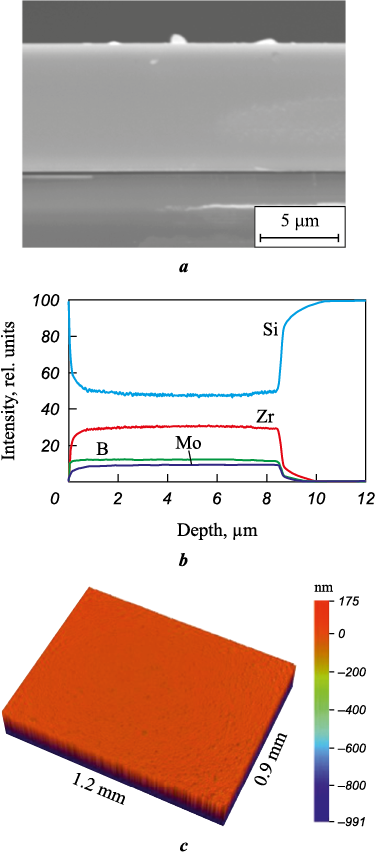
Typical SEM images of the structure, elemental profiles, and three-dimensional surface images (using coating 1 as an example) are shown in Fig. 2.
Fig. 2. Typical SEM micrograph of the cross-sectional |
All samples exhibited a dense, defect-free structure and a similar roughness parameter Ra in the range of 7–8 nm. The structure of the initial coatings was studied in more detail in [25]. According to GDOES data (Fig. 2, b), all elements were uniformly distributed across the thickness of the coatings (refer to the Table).
The thickness of coatings 1, 2, and 3 reached 8.4, 5.7, and 5.6 μm, respectively. The growth rate of sample 1 was 140 nm/min, but switching to HIPIMS mode reduced it by 1.5 times. This reduction can be attributed to self-sputtering effects and the decreased overall sputtering time in HIPIMS pulse mode [30; 31]. It is worth noting that increasing the power during coating deposition under these conditions does not affect the composition or growth rate of the coatings.
According to our previously obtained data [25], all coatings, regardless of the deposition mode, are X-ray amorphous.
Nanoindentation results (refer to the Table) showed that all samples had similar mechanical characteristics: hardness of 11–14 GPa, elastic modulus of 177–208 GPa, and elastic recovery of 37–42 %. It is noteworthy that a hardness level of 10–15 GPa is characteristic of silicide ceramics based on ZrSi2 [1; 32].
Study of high-temperature
oxidation resistance of coatings
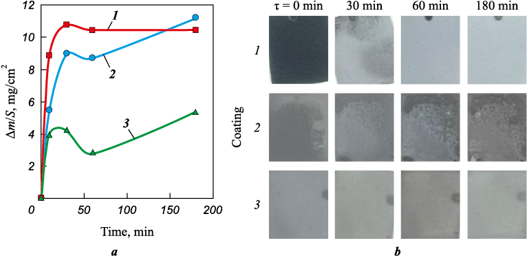
Fig. 3 shows the specific mass change (∆m/S) of the coatings as a function of holding time, as well as the appearance of the coatings before and after annealing at 1000 ºC. For all samples, an increase in the parameter ∆m/S was observed for holding times up to 30 min, associated with the growth of the oxide film on the surface of the coatings. The decrease in this parameter observed for all coatings during the holding period of 30–60 min may be related to the partial evaporation of MoOx . In the range of 60–180 min, the value of ∆m/S increased by 25 and 50 % for samples 1 and 3, respectively, while for coating 2 it remained unchanged. The maximum values of ∆m/S, 11.2 and 10.5 mg/cm2, were recorded for samples 1 and 2, while coating 3, produced in HIPIMS mode at an average power of 2 kW, exhibited the lowest specific mass change of 5.3 mg/cm2, indicating its superior oxidation resistance under stepwise annealing at 1000 °C. The visual analysis of the samples (Fig. 3, b) showed that coatings 1 and 3 maintained their integrity during the tests, with no visible damage (delamination or cracking), whereas coating 2 partially delaminated during the testing.
Fig. 3. Specific mass change (Δm/S) of the coatings as a function of holding time (a) |
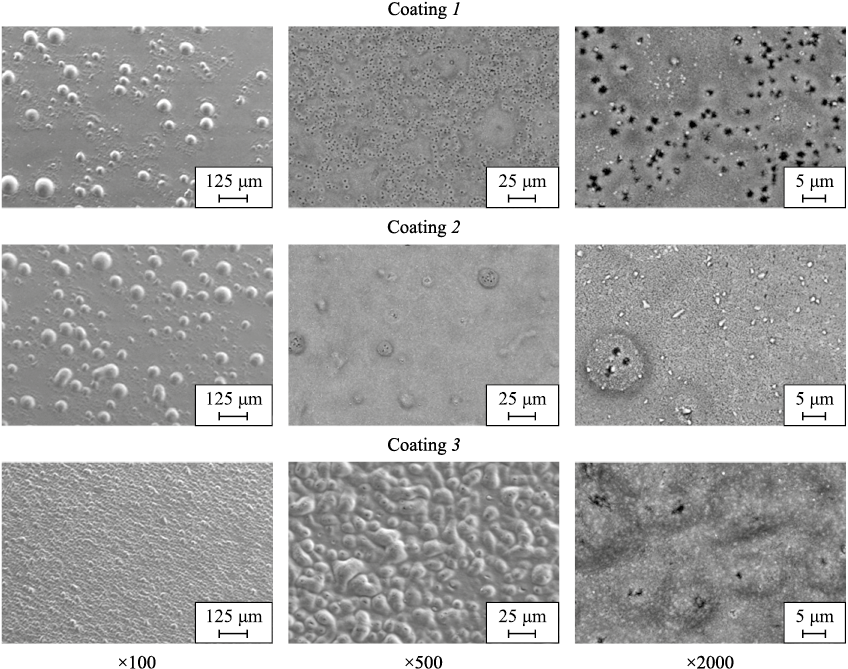
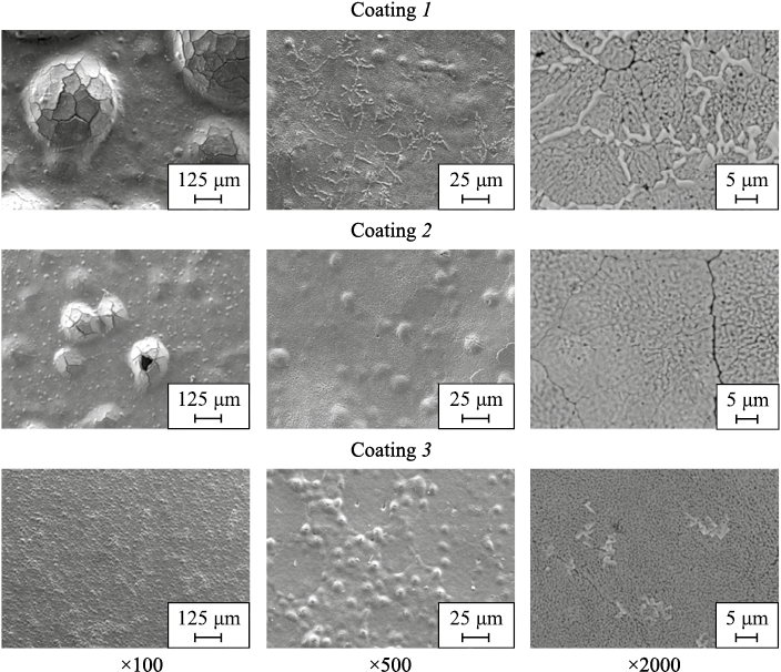
To determine the maximum working temperature at which the coatings retain their protective properties, non-isothermal annealing was conducted in the temperature range of 1100–1500 °C. Fig. 4 presents SEM images of the coating surfaces after annealing at 1100 °C. All samples showed areas of damage (blistering), which could be due to the formation and evaporation of MoOx , as well as phase transformations accompanied by volume changes of the structural components. Similar effects were previously observed in studies of Mo–(Hf, Zr)–Si–B coatings [26]. The size of the local damage areas decreased by 1.3 and 4.0 times when transitioning from coating 1 to coatings 2 and 3, respectively. Particles of ZrOx and ZrSiOx , sized 0.4–1.2 µm, were identified on the surfaces of all samples. According to EDS analysis at points on the surfaces of coatings 1 and 2, the formation of MoOx particles was observed.
Fig. 4. SEM images of the surface of coatings 1, 2, and 3 after annealing at 1100 °С |
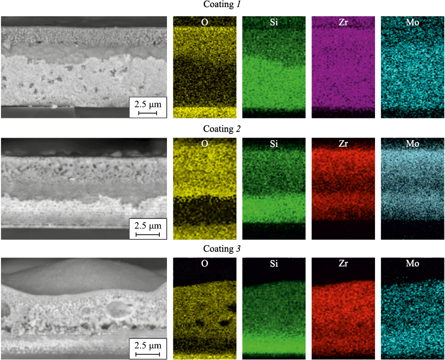
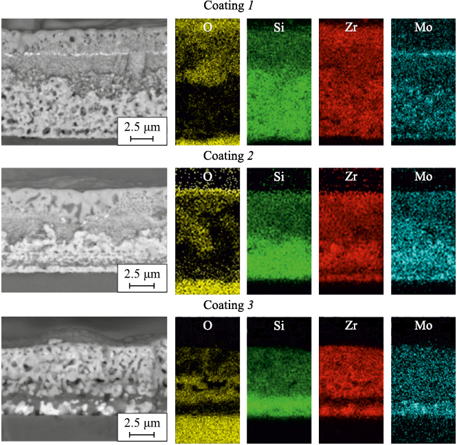
Cross-sectional SEM images and EDS maps of the studied coatings after annealing at 1100 °C are presented in Fig. 5. The obtained data showed that an oxide film of equal thickness (~5.0 µm) formed on the surfaces of coatings 1 and 2, consisting of two layers:
– the upper layer (~2.6 µm thick) consisting of an amorphous phase a-Si:B and nanocrystallites of nc-ZrO2 , nc-ZrSiO4 ;
– the а-Si:В:O layer (~2.4 µm thick).
Fig. 5. Cross-sectional SEM images and EDS maps of coatings 1, 2, and 3 after annealing at 1100 °С |
A porous oxide layer of а-Si:В:O + nc-ZrO2 + nc-ZrSiO4 with a thickness of 4.8 µm formed on the surface of sample 3. Notably, the formation of ZrSiOx and ZrO2 effectively enhances the protective properties of the oxide film by increasing stability and reducing defects in the borosilicate glass layer [33; 34]. After annealing at 1300 °C, the surfaces of samples 1, 2, and 3 exhibited blistering areas of approximately 500, 250, and 15 µm, respectively (Fig. 6), as well as cracks, which could be attributed to oxidation and crystallization processes occurring in the coatings during heating [35; 36]. It is worth mentioning that the presence of cracks facilitates oxygen diffusion into the material, potentially compromising its oxidation resistance [37; 38]. It is worth noting that particles of ZrSiO4 formed in the crack area on the surface of coating 1, which may provide additional healing effects [33].
Рис. 6. SEM images of the surface of coatings 1, 2, and 3 after annealing at 1300 °С |
Fig. 7 shows cross-sectional SEM images of the coatings after annealing at 1300 °C. According to EDS data (mapping and point analysis), the cross-sectional fracture of sample 1 revealed three layers in the oxide film with a thickness of ~6.2 µm:
– the upper porous layer of а-Si:В:O + nc-ZrO2 + nc-ZrSiO4 with a thickness of ~3.0 µm and pore sizes of 0.2–0.6 µm;
– a 200 nm thick layer containing MoOx particles;
– a layer at the “oxide film-coating” interface, consisting a-Si:B:O and nc-ZrO2 .
Fig. 7. Cross-sectional SEM images and EDS maps of coatings 1, 2, and 3 after annealing at 1300 °C |
The oxide film on the surface of sample 2 consisted of а-Si:В:O + nc-ZrO2 + nc-ZrSiO4 with a thickness of ~5.2 µm. The layer near the surface had a porous structure with pore sizes of 0.2–1.2 µm, while the lower layer was dense (see Fig. 7). For coating 3, the thickness of the porous oxide layer а-Si:В:O + nc-ZrO2 + nc-ZrSiO4 was minimal, measuring 4.9 µm. The unoxidized layers of all samples contained crystallites of ZrSi2 and MoSi2 phases.
The results after oxidation annealing at 1300 °C demonstrated that using the HIPIMS method instead of DCMS reduced the thickness of the surface oxygen-containing layer by 16 %. Increasing the power from 1 to 2 kW during HIPIMS deposition further reduced the thickness of the oxide layer by 6 %. This effect may be related to the densification of the structure and the elimination of structural defects in the coatings when transitioning from DCMS to HIPIMS [39; 40]. It is noteworthy that increasing the power during HIPIMS sputtering enhances ionization rates and ion energy, which positively affects the quality of the resulting coatings [41; 42].
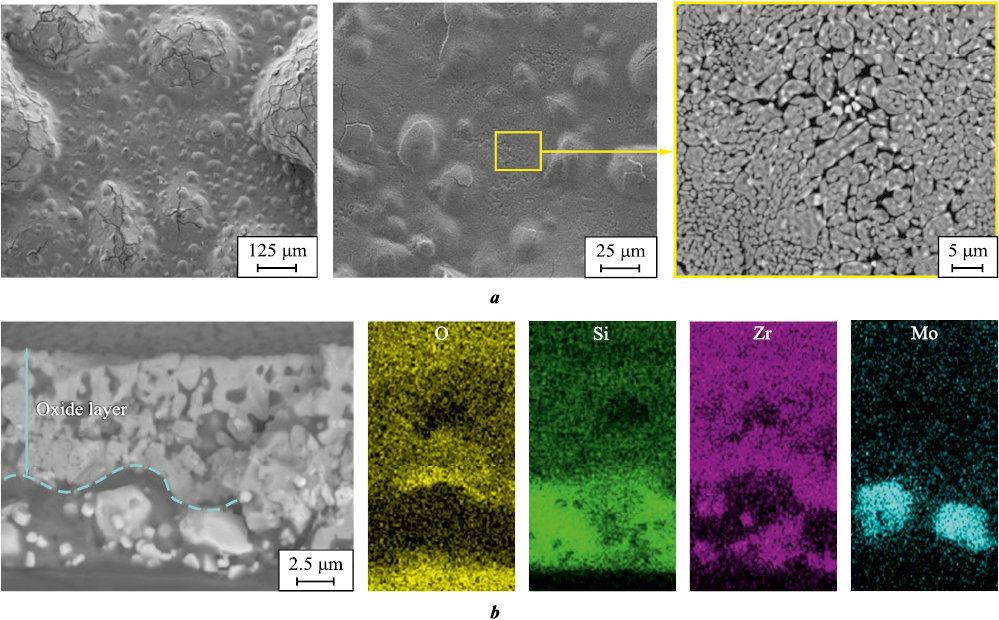
Increasing the annealing temperature to 1500 °C led to the complete oxidation of coatings 2 and 3 due to their small thickness. On the surface of sample 1, in addition to characteristic blistering areas, crack formation was observed (Fig. 8). At higher SEM magnification (×2000), grains of ZrO2 (the brightest areas in the SEM images) with sizes of 0.6–1.8 µm and grains of ZrSiO4 with sizes of 1.2–5.0 µm were identified in an amorphous Si:B matrix (the darkest areas).
Рис. 8. SEM images of the surface (a) and cross-sectional fracture (b) of coating 1 |
According to SEM images and EDS maps of the cross-sectional fracture (Fig. 8), coating 1 retained an oxygen-free layer, indicating its high oxidation resistance at 1500 °C. The thickness of the protective layer а-Si:В:O + nc-ZrO2 + nc-ZrSiO4 , formed on the surface during oxidation was ~8.0 µm. The unoxidized layer contained MoSi2 grains sized 3.6 to 5.0 µm and Zr5Si3 grains sized 0.2 to 1.0 µm. The superior oxidation resistance of coating 1, produced in DCMS mode, can be attributed to its maximum thickness.
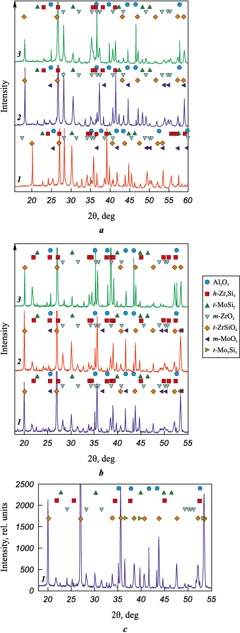
X-ray diffractograms of coatings 1–3 annealed at 1100 °C are presented in Fig. 9, a. Peaks corresponding to the phases o-ZrSi2 (ICDD 032-1499) and t-MoSi2 (ICDD 41-0612), indicative of the unoxidized layer, were identified in all samples. Peaks corresponding to the oxide phases m-ZrO2 (ICDD 07-0343) and t-ZrSiO4 (ICDD 06-0266) were also observed. Coatings 1 and 2 exhibited peaks from the m-MoO2 phase (ICDD 76-1807).
Fig. 9. X-ray diffractograms of coatings 1, 2, and 3 after annealing at 1100 °C (a) |
The crystallite sizes of the main phases, determined using the Debye–Scherrer formula, were similar for all coatings: 50–57 nm for o-ZrSi2 (131) and t-MoSi2 (200), 47–50 nm and 57–70 nm for m-ZrO2 (111) and t-ZrSiO4 (200), respectively. The crystallite sizes of the m-MoO2 (200) phase for coatings 1 and 2 were 61 and 68 nm, respectively.
X-ray diffractograms of coatings annealed at 1300 °C (Fig. 9, b) revealed peaks from the hexagonal phase h-Zr5Si3 (ICDD 79-4988), in addition to the phases t-MoSi2 , m-ZrO2 , and t-ZrSiO4 , indicating a phase transition from the orthorhombic o-ZrSi2 phase to the hexagonal h-Zr5Si3 phase. The crystallite size of h-Zr5Si3 phase increased from 57 to 77 nm when transitioning from coating 1 to coatings 2 and 3.
After heating sample 1 to 1500 °C, the crystallite sizes of the t-ZrSiO4 and m-ZrO2 phases were 50 and 43 nm, respectively, and the sizes of the h-Zr5Si3 and t-MoSi2 phases were 85 and 77 nm, respectively. A partial transition of the t-MoSi2 phase to t-Mo5Si3 was observed (Fig. 9, c). The crystallite size of the t-Mo5Si3 phase, determined from the (002) line, was 57 nm.
Thus, among all the samples studied, coating 1 exhibited the smallest crystallite sizes for both the main phases (h-Zr5Si3 and t-MoSi2 ) and the oxygen-containing phases (t-ZrSiO4 and m-ZrO2 ), indicating its higher thermal stability and enhanced protective properties. This assertion is well supported by the fact that only this sample withstood annealing at 1500 °C. It is noteworthy that Zr–Mo–Si–B coatings are comparable in oxidation resistance to previously studied ZrB2 and ZrSiB coatings [43; 44].
Conclusions
1. Coatings of the Zr–Mo–Si–B system were produced using DCMS and HIPIMS methods with a functionally graded SHS target (ZrSi2–ZrB2–MoSi2)/Cr. Transitioning from DCMS to HIPIMS at P = 1 kW led to an increase in the ionization degree of target component atoms and a threefold rise in the integral intensity of the spectra. Increasing the power from 1 to 2 kW during HIPIMS deposition further doubled this parameter.
2. Regardless of the deposition method (DCMS or HIPIMS), the coatings were X-ray amorphous with a homogeneous structure and uniform elemental distribution throughout their thickness. They exhibited similar values of hardness (11–14 GPa), elastic modulus (177–208 GPa), and elastic recovery (37–42 %). All coatings demonstrated high oxidation resistance in air at t = 1100 and 1300 °C. Transitioning from DCMS to HIPIMS reduced defectiveness and decreased the oxidation depth by 16–21 % at 1300 °C.
3. The 8 µm thick coating showed the highest oxidation resistance at 1500 °C, which is attributed to its thermal stability and the formation of a dense oxide film on the surface with an amorphous matrix of a-Si:B and nanocrystallites of t-ZrSiO4 and m-ZrO2.
References
1. Mudiyanselage Y.C., Ramachandran K., Jayaseelan D. Fabrication and characterisation of ZrSi2 ceramics via reactive hot-pressing. Advances in Applied Ceramics. 2022;121(5–8):166–176. https://doi.org/10.1080/17436753.2022.2139448
2. Geßwein H., Pfrengle A., Binder J.R., Haußelt J. Kinetic model of the oxidation of ZrSi2 powders. Journal of Thermal Analysis and Calorimetry. 2008;91(2):517–523. https://doi.org/10.1007/s10973-007-8461-5
3. Hager M.D., Greil P., Leyens C., Van Der Zwaag S., Schubert U.S. Self-healing materials. Advanced Materials. 2010;22(47):5424–5430. https://doi.org/10.1002/ADMA.201003036
4. Yeom H., Maier B., Mariani R., Bai D., Sridharan K. Evolution of multilayered scale structures during high temperature oxidation of ZrSi2 . Journal of Materials Research. 2016;31(21):3409–3419. https://doi.org/10.1557/jmr.2016.363
5. Song K., Fan J., Li W., Jiang J., Xu Z., Zhang C. Effect of ZrO2 Types on ZrSiO4 formation. Ceramics International. 2019;45(17B):23444–23450. https://doi.org/10.1016/J.CERAMINT.2019.08.048
6. Astapov A.N., Pogozhev Y.S., Prokofiev M.V., Lifanov I.P., Potanin A.Y., Levashov E.A., Vershinnikov V.I. Kinetics and mechanism of high-temperature oxidation of the heterophase ZrSi2–MoSi2–ZrB2 ceramics. Ceramics International. 2019;45(5):6392–6404. https://doi.org/10.1016/j.ceramint.2018.12.126
7. Astapov A.N., Pogozhev Y.S., Prokofiev M. V., Potanin A.Y., Levashov E.A., Vershinnikov V.I., Rabinskiy L.N. Kinetics and mechanism of the oxidation of ZrSi2–MoSi2–ZrB2 ceramics in air at temperatures up to 1400 °C. International Journal of Heat and Mass Transfer. 2019;140:12–20. https://doi.org/10.1016/j.ijheatmasstransfer.2019.05.100
8. Kim J.J., Kim H.G., Ryu H.J. High-temperature oxidation behaviors of ZrSi2 and its coating on the surface of Zircaloy-4 tube by laser 3D printing. Nuclear Engineering and Technology. 2020;52(9):2054–2063. https://doi.org/10.1016/J.NET.2020.02.018
9. Yeom H., Maier B., Mariani R., Bai D., Fronek S., Xu P., Sridharan K. Magnetron sputter deposition of zirconium-silicide coating for mitigating high temperature oxidation of zirconium-alloy. Surface and Coatings Technology. 2017;316:30–38. https://doi.org/10.1016/j.surfcoat.2017.03.018
10. Kim M., Noh H., Lee G.C., Yeom H., Kim T.K., Kim J.M., Kim T.H., Jo H.J., Park H.S., Sridharan K. Flow boiling critical heat flux enhancement in ZrSi2 accident-tolerant fuel cladding with porous structures. Applied Thermal Engineering. 2022;207:118164. https://doi.org/10.1016/J.applthermaleng.2022.118164
11. Liu F., Li H., Gu S., Yao X., Fu Q. Spraying power influence on microstructure and bonding strength of ZrSi2 coating for SiC coated carbon/carbon composites. Ceramics International. 2018;44(6):6619–6625. https://doi.org/10.1016/j.ceramint.2018.01.068
12. Wang L., Fu Q., Zhao F., Zhao Z. Constructing self-healing ZrSi2–MoSi2 coating for C/C composites with enhanced oxidation protective ability. Surface and Coatings Technology. 2018;347:257–269. https://doi.org/10.1016/j.surfcoat.2018.05.002
13. Liu F., Li H., Fu Q., He X., Zhang W. ZrSi2–SiC/SiC gradient coating of micro-structure and anti-oxidation property on C/C composites prepared by SAPS. Coatings. 2022;12(10):1377–2022. https://doi.org/10.3390/coatings12101377
14. Hu M.H., Li K.Z., Li H.J., Wang B., Ma H.L. Double layer ZrSi2–ZrC–SiC/SiC oxidation protective coating for carbon/carbon composites. Surface Engineering. 2014;31(5):335–341. https://doi.org/10.1179/1743294414Y.0000000428
15. Zheng Z., Zhao H., Li Z., Liu X., Wu B., Liu B. Research on microstructure and oxidation resistant property of ZrSi2–SiC/SiC coating on HTR graphite spheres. Ceramics International. 2018;44(5):4795–4800. https://doi.org/10.1016/j.ceramint.2017.12.065
16. Zheng Z.J., Zhou P., Zhao H.S., Li Z.Q., Liu X.X., Zhang K.H., Liu B. ZrSi2–SiC/SiC anti-oxidant coatings prepared on graphite spheres by two-step pack cementation process. Key Engineering Materials. 2017;727:953–958. https://doi.org/10.4028/www.scientific.net/kem.727.953
17. Lifanov I.P., Astapov A.N., Terentieva V.S. Deposition of heat-resistant coatings based on the ZrSi2–MoSi2–ZrB2 system for protection of non-metallic composite materials in high-speed high-enthalpy gas flows. Journal of Physics: Conference Series. 2020;1713(1):012025. https://doi.org/10.1088/1742-6596/1713/1/012025
18. Musil J., Zeman P., Baroch P. Hard nanocomposite coatings. Comprehensive Materials Processing. 2014;4: 325–353. https://doi.org/10.1016/B978-0-08-096532-1.00416-7
19. Kiryukhantsev-Korneev P., Sytchenko A., Pogozhev Y., Vorotilo S., Orekhov A., Loginov P., Levashov E. Structure and properties of Zr–Mo–Si–B–(N) hard coatings obtained by D.C. magnetron sputtering of ZrB2–MoSi2 target. Materials (Basel). 2021;14(8):1932. https://doi.org/10.3390/MA14081932
20. Elmkhah H., Attarzadeh F., Fattah-alhosseini A., Kim K.H. Microstructural and electrochemical comparison between TiN coatings deposited through HIPIMS and DCMS techniques. Journal of Alloys and Compounds. 2018;735:422–429. https://doi.org/10.1016/J.JALLCOM.2017.11.162
21. Kiryukhantsev-Korneev P.V., Sytchenko A.D., Loginov P.A., Orekhov A.S., Levashov E.A. Frequency effect on the structure and properties of Mo–Zr–Si–B coatings deposited by HIPIMS using a composite SHS target. Coatings. 2022;12(10):1570. https://doi.org/10.3390/COATINGS12101570
22. Lattemann M., Ehiasarian A.P., Bohlmark J., Persson P.Å.O., Helmersson U. Investigation of high power impulse magnetron sputtering pretreated interfaces for adhesion enhancement of hard coatings on steel. Surface and Coatings Technology. 2006;200(22-23):6495–6499. https://doi.org/10.1016/J.SURFCOAT.2005.11.082
23. Lu C.Y., Diyatmika W., Lou B.S., Lu Y.C., Duh J.G., Lee J.W. Influences of target poisoning on the mechanical properties of TiCrBN thin films grown by a superimposed high power impulse and medium-frequency magnetron sputtering. Surface and Coatings Technology. 2017;332:86–95. https://doi.org/10.1016/j.surfcoat.2017.06.081
24. Sytchenko A.D., Loginov P.A., Nozhkina A.V., Levashov E.A., Kiryukhantsev-Korneev P.V. Structure and oxidation resistance of Mo–Y–Zr–Si–B coatings deposited by DCMS and HIPIMS methods using mosaic targets. Journal of Composites Science. 2023;7(5):185. https://doi.org/10.3390/jcs7050185
25. Kiryukhantsev-Korneev P.V., Vakhrushev R.A., Sytchenko A.D., Potanin A.Y., Rupasov S.I., Shvyndina N.V., Levashov E.A. Comparative study of the composition and structure of the cathode target (ZrSi2–ZrB2–MoSi2)/Cr and coatings formed using them by the DCMS and HIPIMS methods. Physics of Atomic Nuclei. 2023;86(10):1–6. https://doi.org/10.1134/s1063778823090120
26. Kiryukhantsev-Korneev P.V., Sytchenko A.D., Sviridova T.A., Sidorenko D.A., Andreev N.V., Klechkovskaya V.V., Polčak J., Levashov E.A. Effects of doping with Zr and Hf on the structure and properties of Mo–Si–B coatings obtained by magnetron sputtering of composite Targets. Surface and Coatings Technology. 2022;442:128141. https://doi.org/10.1016/j.surfcoat.2022.128141
27. Kiryukhantsev-Korneev F.V. Possibilities of glow discharge optical emission spectroscopy in the investigation of coatings. Russian Journal of Non-Ferrous Metals. 2014;55(5):494–504. https://doi.org/10.3103/S1067821214050137
28. Sytchenko A.D., Kiryukhantsev-Korneev P.V. Plasma diagnostics during deposition of Zr–B–N coatings by magnetron sputtering of UHTC ceramic in DCMS and HIPIMS modes. Journal of Physics: Conference Series. 2021;2064(1):012062. https://doi.org/10.1088/1742-6596/2064/1/012062
29. Bobzin K., Brögelmann T., Kruppe N.C., Engels M. Influence of DCMS and HPPMS in a DCMS/HPPMS hybrid process on plasma and coating properties. Thin Solid Films. 2016;620:188–196. https://doi.org/10.1016/J.TSF.2016.07.079
30. Samuelsson M., Lundin D., Jensen J., Raadu M.A., Gudmundsson J.T., Helmersson U. On the film density using high power impulse magnetron sputtering. Surface and Coatings Technology. 2010;205(2):591–596. https://doi.org/10.1016/J.SURFCOAT.2010.07.041
31. Lakhonchai A., Chingsungnoen A., Poolcharuansin P., Pasaja N., Bunnak P., Suwanno M. Comparison of the structural and optic Al properties of amorphous silicon thin films prepared by direct current, bipolar pulse, and high-power impulse magnetron sputtering methods. Thin Solid Films. 2022;747:139140. https://doi.org/10.1016/J.TSF.2022.139140
32. Grigoriev O.N., Galanov B.A., Kotenko V.A., Ivanov S.M., Koroteev A. V., Brodnikovsky N.P. Mechanical properties of ZrB2–SiC(ZrSi2) ceramics. Journal of the European Ceramic Society. 2010;30(11):2173–2181. https://doi.org/10.1016/J.JEURCERAMSOC.2010.03.022
33. Ren X., Sun X., Wang W., Mo H., Feng P., Guo L.T., Li Z. Anti-oxidation modification behaviors and mechanisms of ZrB2 phase on Si-based ceramic coatings in aerobic environment with wider temperature region. Journal of Alloys and Compounds. 2018;769:387–396. https://doi.org/10.1016/J.JALLCOM.2018.07.300
34. Liu, F., Li, H., Gu, S., Yao, X., Fu, Q. Microstructure and oxidation Property of CrSi2–ZrSi2–Y2O3/SiC coating prepared on C/C composites by supersonic atmosphere plasma spraying. Surface and Coatings Technology. 2019;374:966–974. https://doi.org/10.1016/j.surfcoat.2019.06.087
35. Fu T., Shen F., Zhang Y., Yu L., Cui K., Wang J., Zhang X. Oxidation protection of high-temperature coatings on the surface of Mo-based alloys. A Review. Coatings. 2022;12(2):141. https://doi.org/10.3390/coatings12020141
36. Solak N., Ustel F., Urgen M., Aydin S., Cakir A.F. Oxidation behavior of molybdenum nitride coatings. Surface and Coatings Technology. 2003;174-175:713–719. https://doi.org/10.1016/s0257-8972(03)00702-3
37. Xu M., Guo L., Wang H. Crack evolution and oxidation failure mechanism of a SiC-ceramic coating reactively sintered on carbon/carbon composites. Materials (Basel). 2021;14(24):7780. https://doi.org/10.3390/MA14247780
38. Yan K., Xiang Y., Yu H., Li Z., Wu Y., Sun J. Effect of irregular microcracks on the hot corrosion behavior and thermal shock resistance of YSZ thermal barrier coatings. Surface and Coatings Technology. 2022;431:128038. https://doi.org/10.1016/J.SURFCOAT.2021.128038
39. Lin H., Wang C., Lai Z., Kuang T., Djouadi M.A. Microstructure and mechanical properties of HfBx Coatings deposited on cemented carbide substrates by HiPIMS and DCMS. Surface and Coatings Technology. 2023;452:129119. https://doi.org/10.1016/J.SURFCOAT.2022.129119
40. Shu R., Du H., Sadowski G., Dorri M.M., Rosen J., Sortica M.A., Primetzhofer D., Lundin D., le Febvrier A., Eklund P. Multicomponent TixNbCrAl nitride films deposited by Dc and high-power impulse magnetron sputtering. Surface and Coatings Technology. 2021;426:127743. https://doi.org/10.1016/j.surfcoat.2021.127743
41. Nouvellon C., Michiels M., Dauchot J.P., Archambeau C., Laffineur F., Silberberg E., Delvaux S., Cloots R., Konstantinidis S., Snyders R. Deposition of titanium oxide films by reactive high power impulse magnetron sputtering (HiPIMS): Influence of the peak current value on the transition from metallic to poisoned regimes. Surface and Coatings Technology. 2012;206(16):3542–3549. https://doi.org/10.1016/j.surfcoat.2012.02.034
42. Lu X., Sui X., Kang J., Zhang X., Miao X.X., Wang J., Hao J. Effect of peak current on the microstructure, mechanical properties and tribological behavior of MoxN coatings deposited by high power impulse magnetron sputtering. Tribology International. 2023;189:108955. https://doi.org/10.1016/j.triboint.2023.108955
43. Kiryukhantsev-Korneev F.V., Lemesheva M.V., Shvyndina N.V., Levashov E.A., Potanin, A.Y. Structure, mechanical properties, and oxidation resistance of ZrB2 , ZrSiB, and ZrSiB/SiBC coatings. Protection of Metals and Physical Chemistry of Surfaces. 2018;54(6):1147–1156. https://doi.org/10.1134/S207020511806014X
44. Kiryukhantsev-Korneev P.V., Sytchenko A.D., Kozlova N.S., Zabelina E.V., Sidorenko D.A., Levashov E.A., Feng P. Effect of nitrogen on the structure and properties of Zr–Si–B–N coatings deposited by magnetron sputtering. Surface and Coatings Technology. 2023;474:130042. https://doi.org/10.1016/j.surfcoat.2023.130042
About the Authors
A. D. ChertovaRussian Federation
Alina D. Chertova – Cand. Sci. (Eng.), Junior Researcher, Laboratory “In situ Diagnostics of Structural Transformations” , Scientific-Educational Center of Self-Propagating High-temperature Synthesis of MISIS–ISMAN (SHS-Center)
4 Leninsky Prosp., Moscow 119049, Russia
F. I. Chudarin
Russian Federation
Fedor I. Chudarin – Laboratory Assistant, SHS-Center of MISIS–ISMAN
4 Leninsky Prosp., Moscow 119049, Russia
I. O. Vakhrusheva
Russian Federation
Irina O. Vakhrusheva – Project Engineer, SHS-Center of MISIS–ISMAN
4 Leninsky Prosp., Moscow 119049, Russia
Yu. Yu. Kaplansky
Russian Federation
Yuri Yu. Kaplansky – Cand. Sci. (Eng.), Researcher, Laboratory “In situ diagnostics of structural transformations” , SHS-Center of MISIS–ISMAN
4 Leninsky Prosp., Moscow 119049, Russia
X. Ren
China
Xuanru Ren – Dr. Sci., Professor
Zhengzhou 450046, China
P. Feng
China
Peizhong Feng – Dr. Sci., Professor
Xuzhou 221116, China
E. A. Levashov
Russian Federation
Evgeniy A. Levashov – Dr. Sci. (Eng.), Professor, Academician of the Russian Academy of Natural Sciences, Head of the Department of Powder Metallurgy and Functional Coatings, NUST MISIS; Head of SHS-Center of MISIS–ISMAN
4 Leninsky Prosp., Moscow 119049, Russia
Ph. V. Kiryukhantsev-Korneev
Russian Federation
Philipp V. Kiryukhantsev-Korneev – Dr. Sci. (Eng.), Professor of the Department of Powder Metallurgy and Functional Coatings, Head of the Laboratory «In situ Diagnostics of Structural Transformations”, SHS-Center of MISIS–ISMAN
4 Leninsky Prosp., Moscow 119049, Russia
Review
For citations:
Chertova A.D., Chudarin F.I., Vakhrusheva I.O., Kaplansky Yu.Yu., Ren X., Feng P., Levashov E.A., Kiryukhantsev-Korneev P.V. Oxidation-resistant Zr–Mo–Si–B coatings deposited by DCMS and HIPIMS methods. Powder Metallurgy аnd Functional Coatings (Izvestiya Vuzov. Poroshkovaya Metallurgiya i Funktsional'nye Pokrytiya). 2024;18(4):55-68. https://doi.org/10.17073/1997-308X-2024-4-55-68
JATS XML


